Split-torque gear box

a gearbox and torque technology, applied in gearing, transportation and packaging, hoisting equipment, etc., can solve the problems of increasing the cost of production, so as to reduce the weight and simplify the manufacturing process. , the effect of reducing the weigh

Active Publication Date: 2005-01-20
SIKORSKY AIRCRAFT CORP
View PDF68 Cites 47 Cited by
  • Summary
  • Abstract
  • Description
  • Claims
  • Application Information

AI Technical Summary

Benefits of technology

[0010] The present invention therefore provides a split torque gearbox system that is relatively uncomplicated and inexpensive to...

Problems solved by technology

While this prior art split torque system has managed to increase the horsepower-to-weight ratio in some situations, especially where total horsepower involved is substantial and where multiple input drive paths from different engines are present, this conventional approach still requires a relatively large weight and a relatively large volume.
Moreover, many...

Method used


Image

  • Split-torque gear box
  • Split-torque gear box
  • Split-torque gear box

Examples


Embodiment Construction

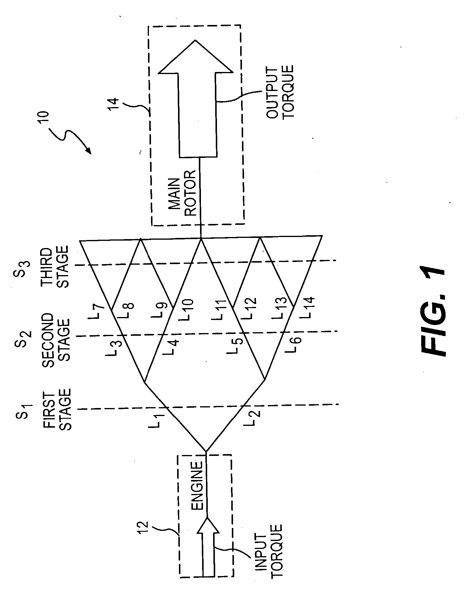
[0022]FIG. 1 illustrates a general schematic view of a split torque gearbox system 10. In the case of a rotary wing aircraft transmission, the system 10 is interposed between one or more gas turbine engines (illustrated schematically at 12) and a rotor assembly (illustrated schematically at 14).

[0023] The split torque gearbox system 10 generally includes three stages S1, S2 and S3. Each stage includes a plurality of links L1-Ln. Each link represents gears which splits the torque from the engine 12. Each link is preferably structurally designed based on the transmitted portion of the total load for that link. That is, because of the equality of the load split, each link need not be over designed for a greater capacity as was heretofore required to assure transmission of an unequally split load.

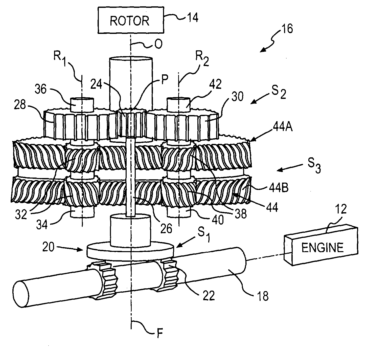
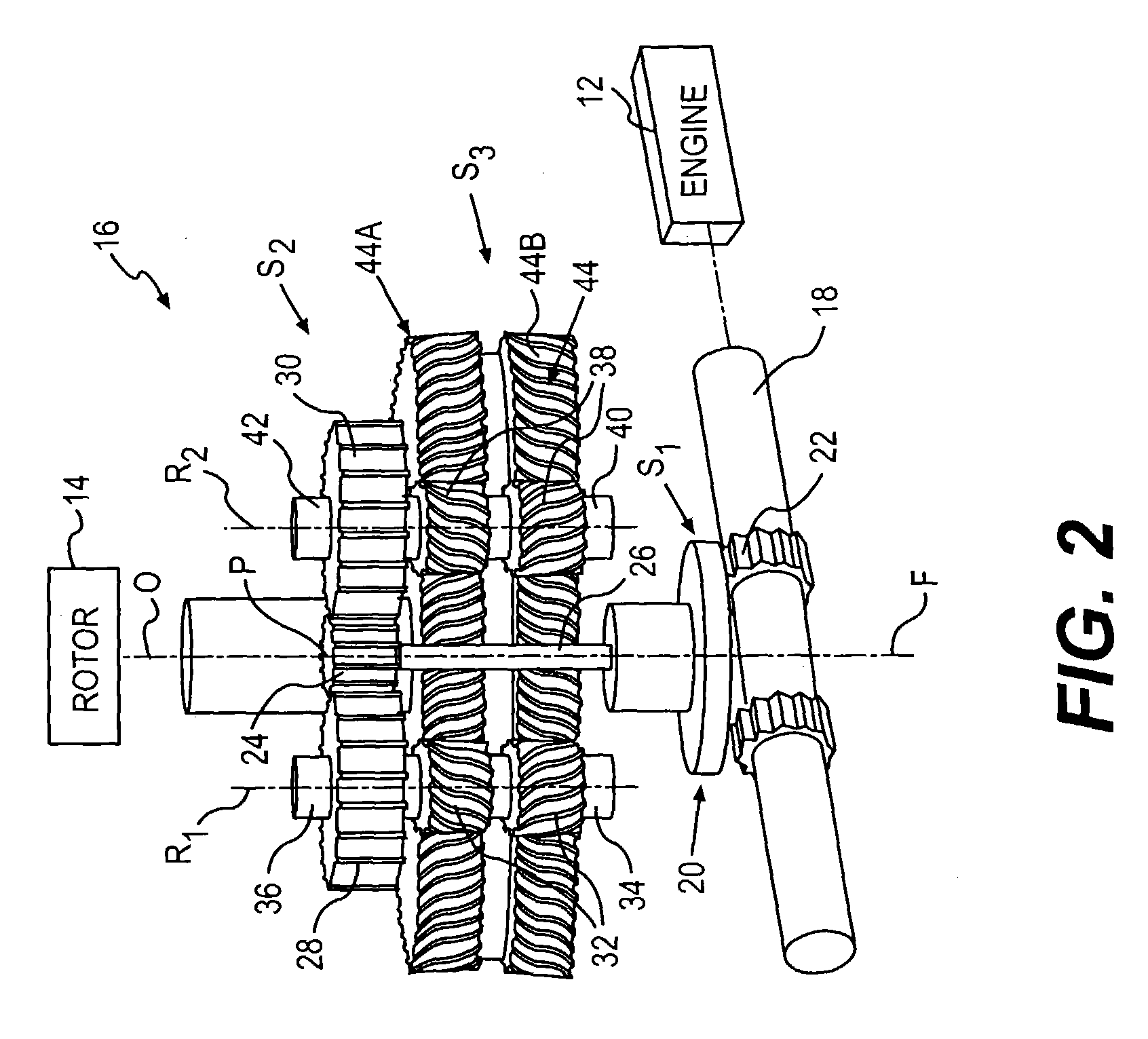
[0024] Referring to FIG. 2, a split torque module 16 of the gearbox system 10 is illustrated. Each split torque module 16 generally includes the three stages S1, S2 and S3. The split torque m...


PUM


Abstract

A split torque gearbox system provides a multiple path, three stage power gear train that transmits torque from a high-speed engine to a low speed output shaft, while providing equal gear load distribution with a floating pinion in the second stage of reduction. The number of the split modules in the gearbox depends on gearbox configuration, number of high speed input shafts, and transmitted power. The split modules are located around a last stage output gear that combines power from each module and transmits the power to an output such as a main rotor system.

Description

BACKGROUND OF THE INVENTION [0001] The present invention relates to a split torque gearbox, and more particularly to a rotary wing aircraft gearbox system. [0002] A gearbox system of a rotorcraft or propeller-driven aircraft transfers power from a turbine engine to the rotor or propeller of the rotorcraft or aircraft. A typical system may direct power from several turbine engines to a single rotor or propeller. Since the rotational velocity of the rotor or propeller is significantly lower than the rotational velocity of the turbine engines, the turbine engine rotational velocity must be reduced by the gearbox system. In reducing the rotational velocity of the turbine engine output, torque is increased through a series of intermediate gear stages and shafts, before the final output drive is provided to the rotor. Relatively large gears are required near the final output drive to handle the high torque supplied to the rotors. [0003] One prior art system includes a number of gears arra...

Claims


Application Information

Patent Timeline
IPC IPC(8): B64C27/12F16H1/22
CPCB64C27/12F16H1/22Y10T74/19084Y10T74/19623Y10T74/19647F16H1/222
Inventor GMIRYA, YURIY
Owner SIKORSKY AIRCRAFT CORP
Why Eureka
Try Eureka