Deaeration of water and other liquids

a technology of water and other liquids, applied in the direction of liquid degasification, water/sewage treatment by degassing, separation process, etc., can solve the problems of difficult to achieve the gas absorption under these conditions, undesirable flavor degradation, and dissolved air or oxygen contributing to undesired foaming

Inactive Publication Date: 2005-01-20
PRAXAIR TECH INC
View PDF30 Cites 22 Cited by
  • Summary
  • Abstract
  • Description
  • Claims
  • Application Information

AI Technical Summary

Benefits of technology

[0012] (d) feeding said liquid into a vessel wherein a gas space is maintained over said liquid, wherein the pressure of said gas space is less than the pressure upstream of said means, whereby said gaseous component evolves from said liquid in said vessel, and separately withdrawing said evolved gaseous component, and said liquid from which said gaseous component has evolved, from said vessel at rates which maintain the pressure of said gas space below the pressure upstream of said means.
[0013] As used herein, gas is considered to be “contained” in a liquid if the gas is pres...

Problems solved by technology

The dissolved air or oxygen contributes to undesired foaming, undesirable degradation of flavor, and interference with the dissolution of carbon dioxide into the water during the manufacture of carbonated beverages.
At these conditions, equilibrium favors gas removal, but achieving desired gas absorption under these conditions is difficult.
This usually means that little carbon dioxide is absorbed int...

Method used


Image

  • Deaeration of water and other liquids
  • Deaeration of water and other liquids
  • Deaeration of water and other liquids

Examples


example 1

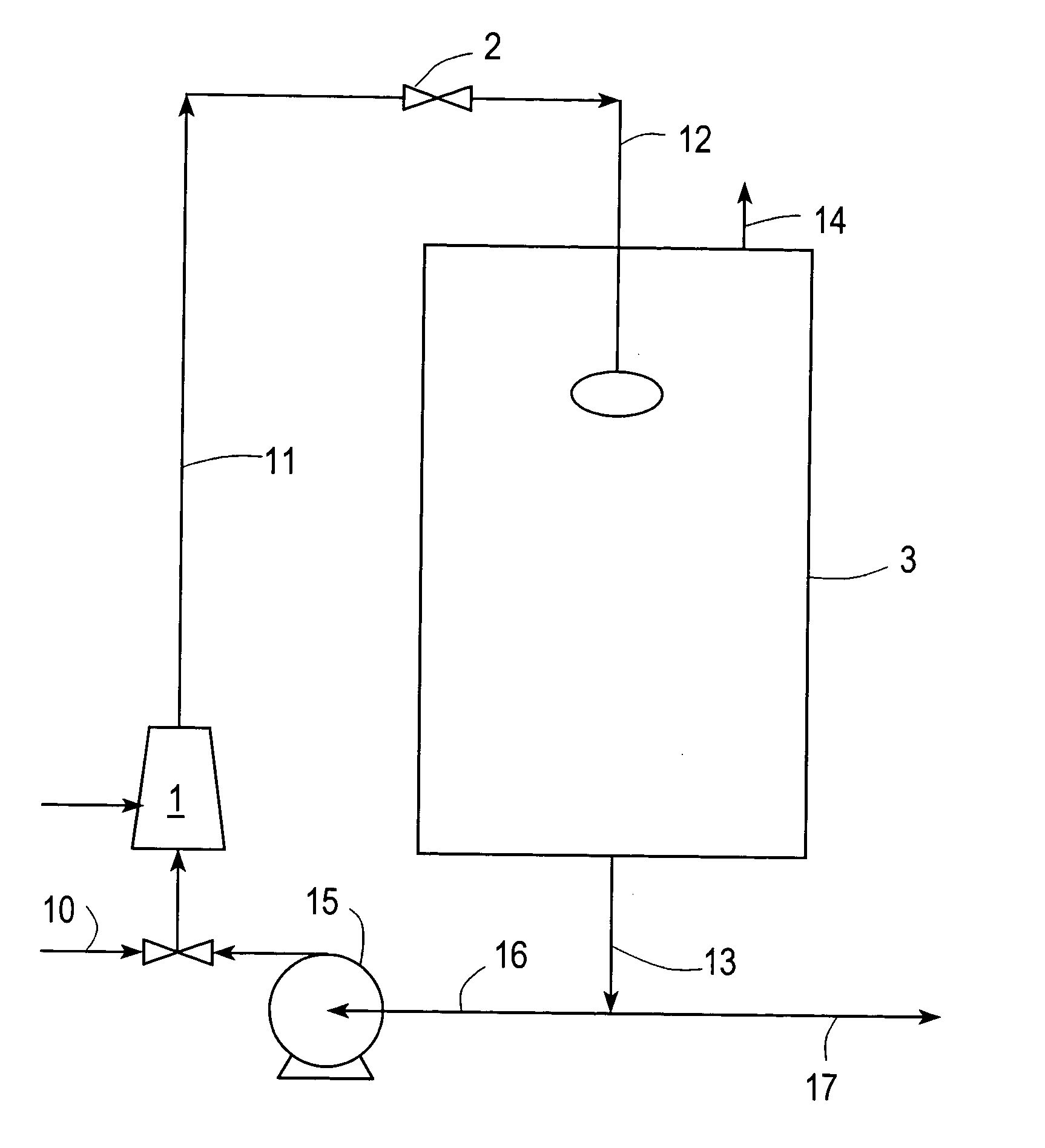
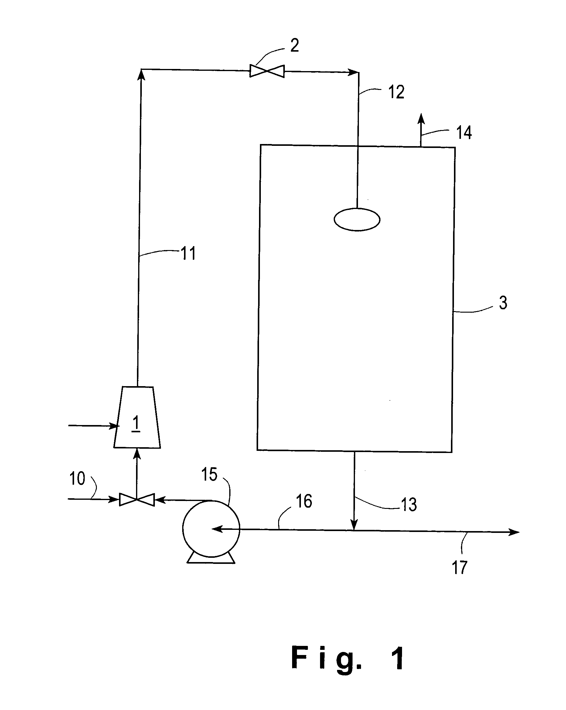
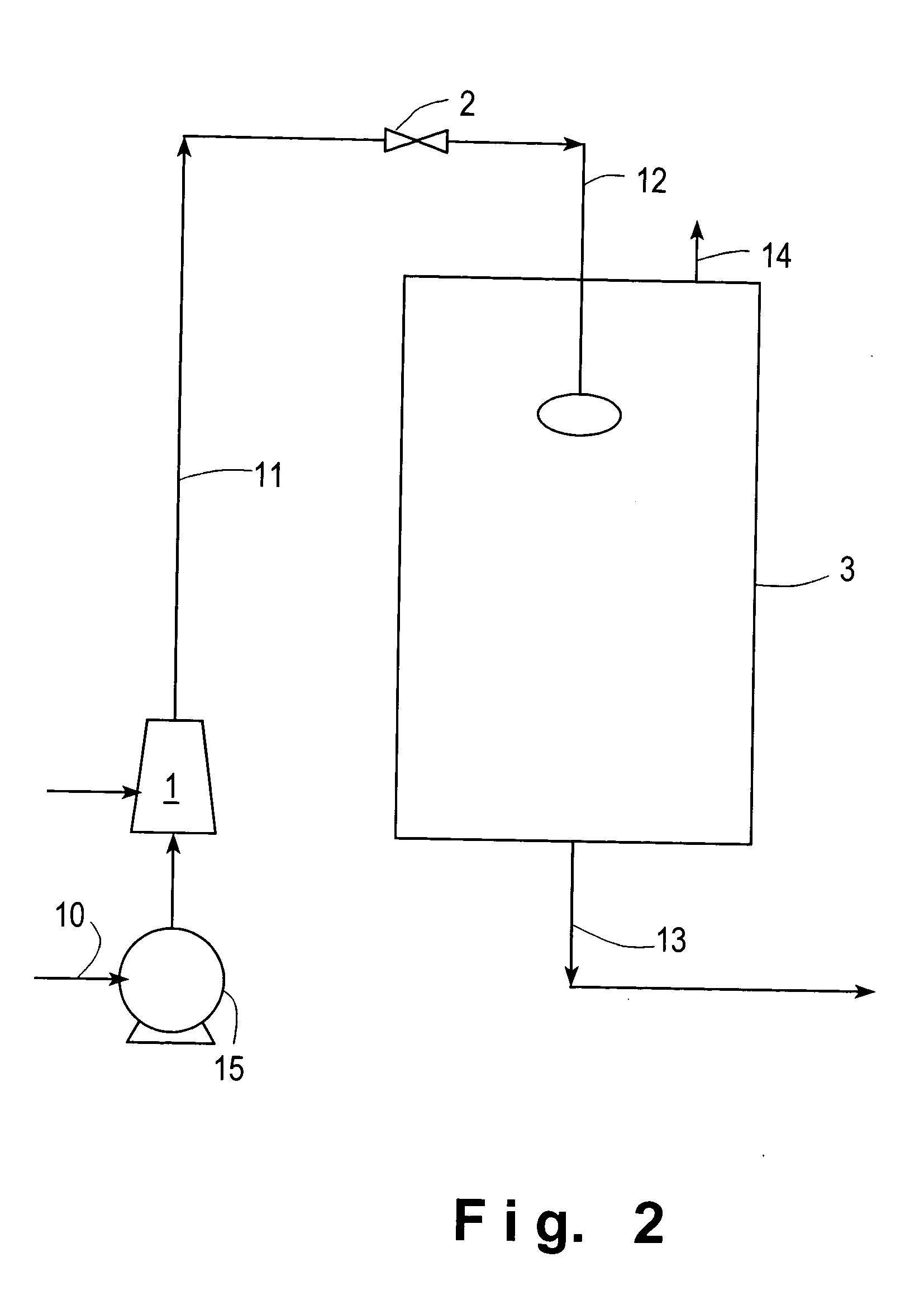
[0041] This example demonstrates dissolving CO2 into the water and then liberating some of the CO2 to strip oxygen, in the embodiment depicted in FIG. 2. Table 1 contains the results.

TABLE 1Results of lab tests, showing CO2 dissolution atsupersonic injector under high pressure and CO2liberation in the break-tank at low pressure withstripping of oxygen.Run No.123Water flow rate (L / hr)210021002100Gas flow rate (L / min)40.7054.8654.10Pressure (kg / cm2)at:outlet of pump 154.244line 113.22.82.8line 122.82.83line 13443.8Oxygen content (ppm) at:outlet of pump 158.137.555.6line 116.324.912.8line 127.826.163line 131.90.950.52Carbon dioxide content (v / v) at:outlet of pump 15000line 110.9721.341.3line 120.9781.711.5line 130.680.760.33Temperature (C) at:line 11262530vessel 3 (liquid)262432

[0042] As can be seen from Table 1, CO2 was dissolved under high pressure and then re-liberated in the break-tank, and deaeration expressed as reduction of oxygen content was achieved.

example 2

[0043] Tests at a bottler showed that CO2 was retained in the vessel 3 (break tank) much better than expected. One might expect that air would not elute if the CO2 did not leave, but excellent deaeration was still obtained.

[0044] The system was of the type depicted in

[0045]FIG. 2, with the addition of a plate type chiller system between the injector 1 and the valve 2.

[0046] CO2 was injected into water at 30° C., at 30 psig of pressure. About 20 meters of 4″ tubing was provided before the chiller which reduced the water temperature to 7° C. After the chiller, the water then flowed another 15 meters to an open atmosphere tank. No spray device was used; the water simply flowed out of an open pipe. The deaerated water then flowed out of the bottom of the tank to a carbonator. The flow rate of the water was 6 Nm3 / hr.

[0047] At the temperature and pressure of the line after the chiller, the saturation level of CO2 was estimated to be 2.05 volumes of CO2 (standard temperature and pressu...


PUM

PropertyMeasurementUnit
Fractionaaaaaaaaaa
Fractionaaaaaaaaaa
Fractionaaaaaaaaaa

Abstract

Liquid such as water is deaerated by dissolving stripping gas such as carbon dioxide into the water while maintaining pressure, reducing the pressure, and then feeding the liquid into a vessel wherein a gas space is maintained over said water, wherein the pressure of said gas space is less than the pressure upstream, and separately withdrawing degassed liquid and evolved gas from said vessel at rates which maintain the pressure of said gas space below the pressure upstream of said means.

Description

FIELD OF THE INVENTION [0001] The present invention relates to the removal of dissolved or absorbed gas, such as oxygen or air, from water or other liquids. BACKGROUND OF THE INVENTION [0002] In many processes that employ water, it is desirable that the content of dissolved air or oxygen in the water be lower than the content found in the water as it comes in from a municipal feed line, or as it is recovered in a recycle stream from another processing stage. This is especially the case in processes that employ water in the manufacture of beverages. The dissolved air or oxygen contributes to undesired foaming, undesirable degradation of flavor, and interference with the dissolution of carbon dioxide into the water during the manufacture of carbonated beverages. [0003] The removal of dissolved oxygen is also important in many other industrial processes, such as preparation of syrups and edible oils. [0004] The removal of dissolved gas such as air or oxygen from the water or other liqu...

Claims


Application Information

Patent Timeline
IPC IPC(8): B01D19/00C02F1/20C02F1/74
CPCB01D19/0005C02F1/74C02F1/20
Inventor WILLIAMS, WILLIAM ROBERTPRADO, MARCILIO PAIVANOGUEIRA, LUIS CLAUDIO DIAS
Owner PRAXAIR TECH INC
Why Eureka
Try Eureka