Vehicular electrical equipment unit heating and cooling system and hybrid vehicle

a technology of electrical equipment and heating equipment, which is applied in the direction of engine-driven generators, electric propulsion mounting, transportation and packaging, etc., can solve the problems of shortening the life of the battery, reducing the heating and cooling performance of the battery, and damage to the inverter, so as to reduce the volume of the second air passageway including the wall portion, the effect of efficient heating and efficient cooling

Active Publication Date: 2005-01-20
HONDA MOTOR CO LTD
View PDF8 Cites 79 Cited by
  • Summary
  • Abstract
  • Description
  • Claims
  • Application Information

AI Technical Summary

Benefits of technology

[0016] According to the construction, since the necessity is obviated of an exclusive wall portion for defining the second air passageway, the volume of the second air passageway including the wall portion can be decreased, and the number of components can be decreased.
[0023] According to the first aspect of the invention, there are provided superior advantages that the battery can be cooled efficiently by passing air in the passenger compartment into the first air passageway in the electrical equipment unit by shutting off the second air passageway, and additionally that the battery can be heated efficiently by circulating air in the closed circuit made by connecting the second air passageway with the first air passageway. Moreover, since the air is circulated in the closed circuit when the battery is being heated, resulting in no air communication with the passenger compartment during the heating of the battery, there is provided a superior advantage that the heating process of the battery has no effect on the control of the passenger compartment temperature.
[0024] According to the second aspect of the invention, since the volume of the second air passageway including the wall portion can be decreased, the heating and cooling system can be made compact in size, and the costs can be attempted to be decreased by decreasing the number of components involved.
[0025] According to the third aspect of the invention, since air can be circulated in the closed circuit made by connecting the second air passageway with the first air passageway, the battery can be heated quickly, and additionally, since the amount of air can be increased when air in the passenger compartment that is induced from the air inlet is passed through the first air passageway and is then discharged from the air outlet, the battery can be cooled efficiently.
[0026] According to the fourth aspect of the invention, since the first and second opening and closing sections can both be opened and closed with the force based on the flow of air passing through the first air passageway, the necessity is obviated of an electrical control for opening and closing the first and second opening and closing sections, thereby making it possible to attempt to simplify the construction of the system, decrease the number of components involved and decrease the costs.

Problems solved by technology

Incidentally, while the battery and the inverter entrains heat when they are in operation, in the event that the temperature of the battery increases too high, the charging and discharging performance of the battery is decreased, and the life of the battery is made shorter, and in the event that a certain heat-resistant temperature is exceeded, there is caused a risk that the inverter is damaged.
In addition, since the charging and discharging performance of the battery is also decreased when the temperature thereof becomes too low, a heating apparatus is required.

Method used


Image

  • Vehicular electrical equipment unit heating and cooling system and hybrid vehicle
  • Vehicular electrical equipment unit heating and cooling system and hybrid vehicle
  • Vehicular electrical equipment unit heating and cooling system and hybrid vehicle

Examples


Embodiment Construction

[0035] Hereinafter, embodiments of a vehicular electrical equipment heating and cooling system according to the invention and a hybrid vehicle equipped with the system will be described by reference to FIGS. 1 to 7.

[0036] The vehicular electrical equipment unit heating and cooling system according to an embodiment is installed in a so-called hybrid vehicle driven by transmitting the driving force of at least either of an engine and a motor to driving wheels thereof.

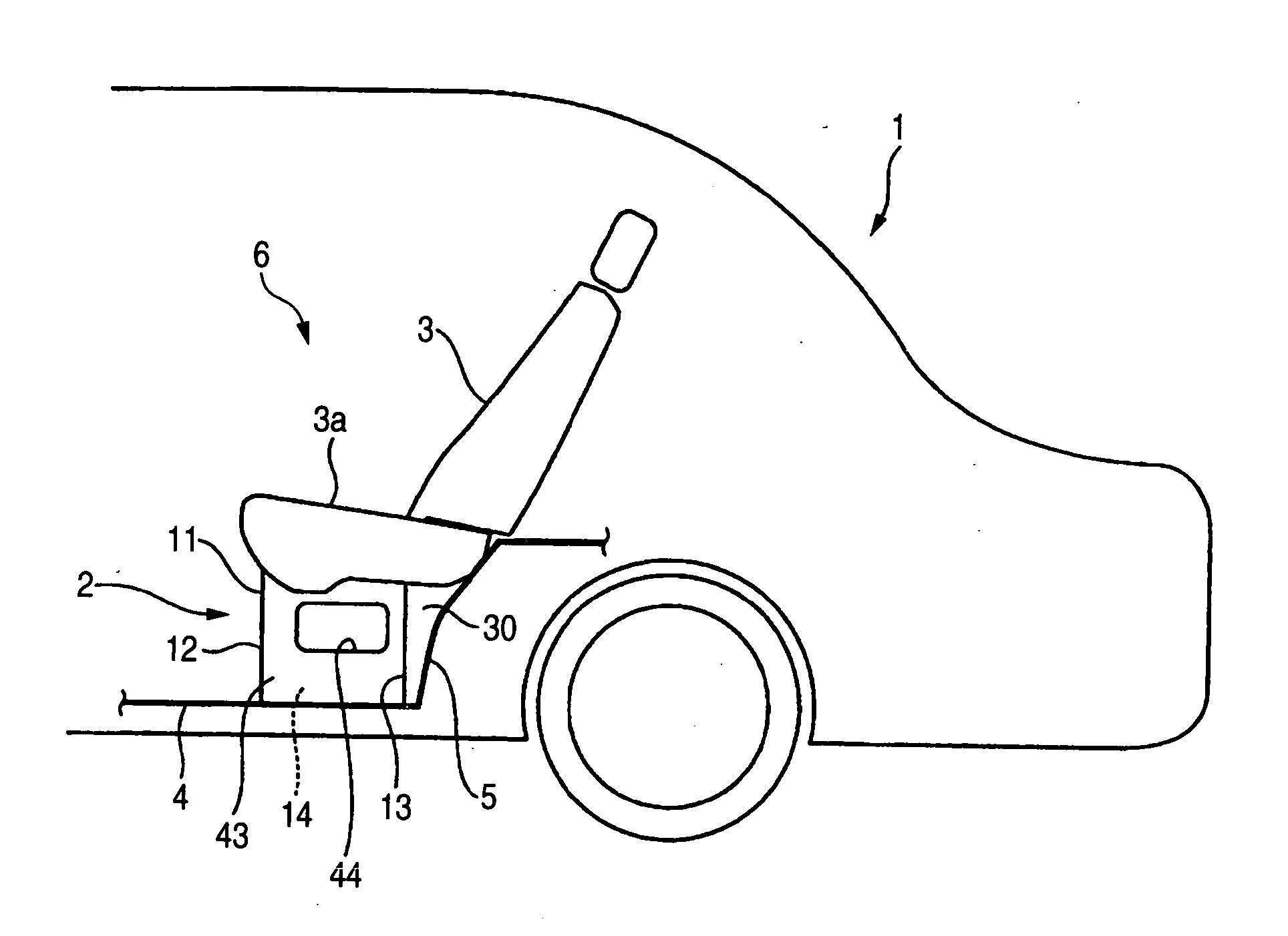
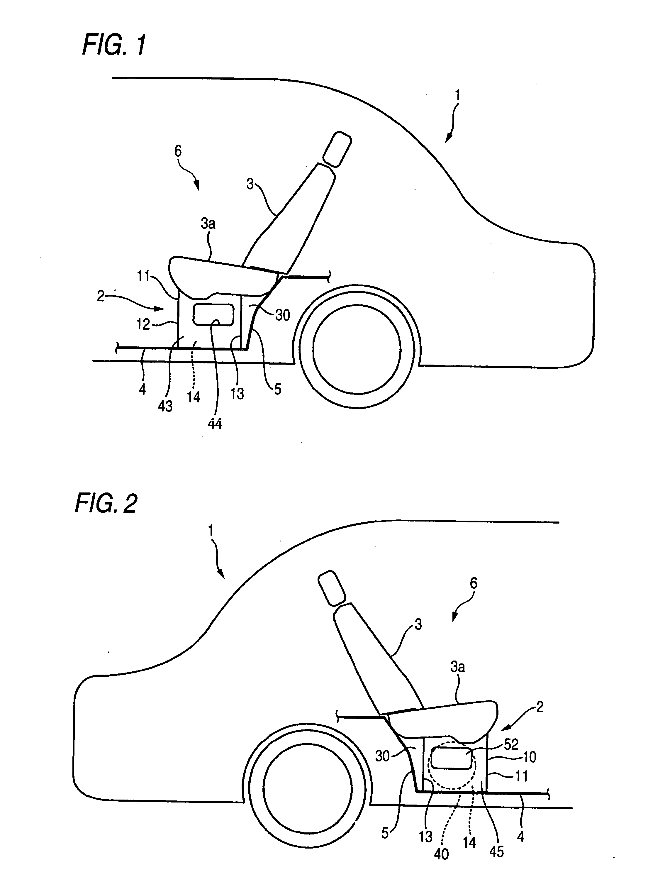
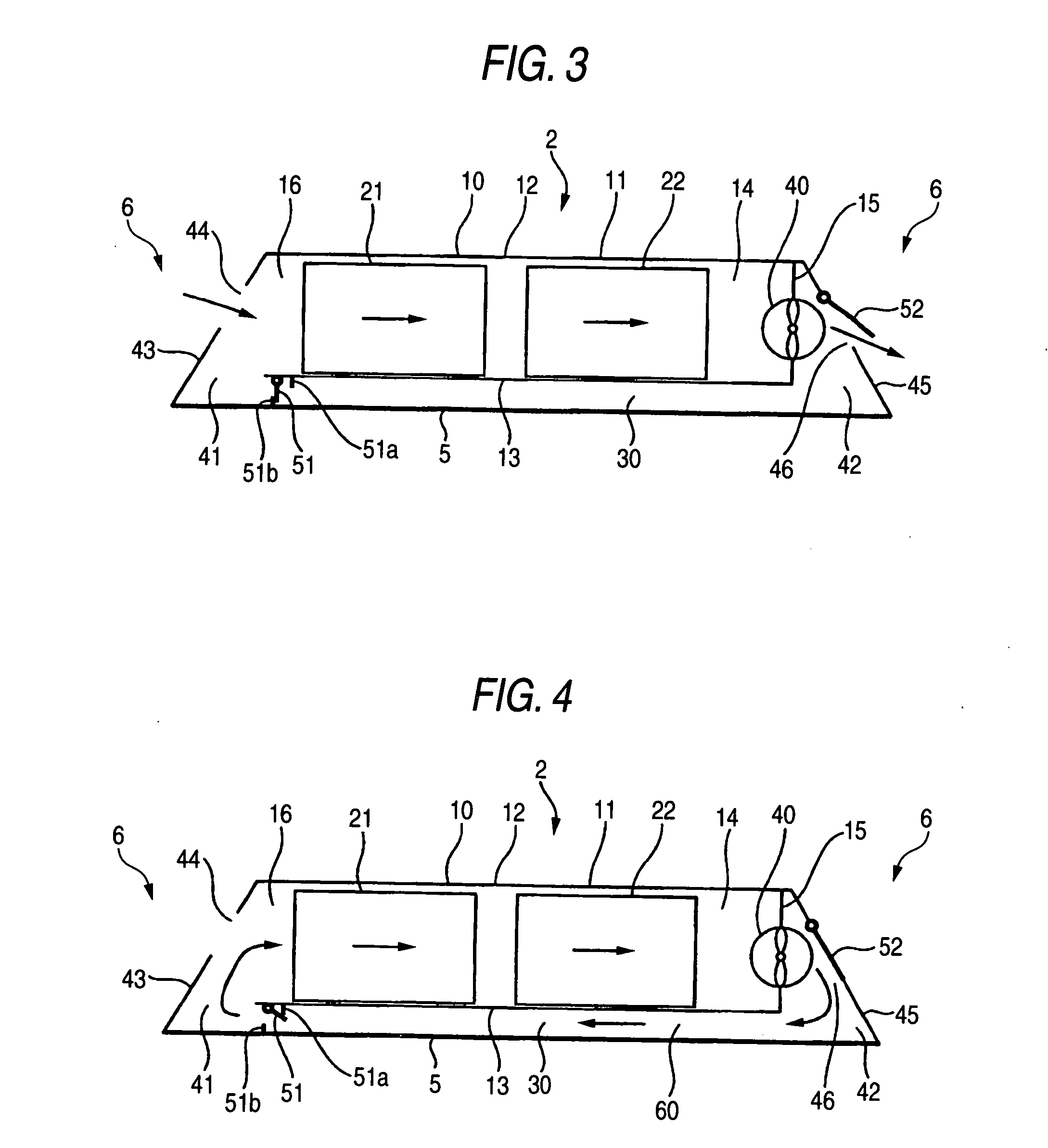
[0037]FIG. 1 is a perspective view of a left-hand side of a rear part of a hybrid vehicle 1, FIG. 2 is a perspective view of a right-hand side of the rear part of the same vehicle, and FIGS. 3 and 4 are transverse cross-sectional views of a vehicular electrical equipment unit heating and cooling system 2. Note that in the following description, “front”, “rear”, “left” and “right” indicate directions as viewed from the driver.

[0038] In the hybrid vehicle 1, when the motor is energized from a battery which is a direct cu...


PUM


Abstract

A vehicular electrical equipment unit heating and cooling system includes a vehicular electrical equipment unit 10 including a battery 21 and an inverter YBU5 22 which are accommodated in a primary air passageway 14, an air inlet 44 through which air in a passenger compartment 6 is admitted to the primary air passageway 14, an air outlet 46 through which air flowing in the primary air passageway 14 is discharged to the outside of the electrical equipment unit 10, a subsidiary air passageway 30 connected to and cut off from the primary air passageway 14 to make a closed circuit 60 when connected to the primary air passageway 14, and a fan 40 for generating a flow of air in the primary air passageway 14.

Description

BACKGROUND OF THE INVENTION [0001] The present invention relates to a vehicular electrical equipment unit heating and cooling system for heating or cooling an electrical equipment unit on an electric vehicle which runs only by the driving force of a motor or a so-called hybrid vehicle which runs by driving forces of an engine and a motor. [0002] In the electric vehicle or hybrid vehicle, when electricity is supplied from the battery which is a direct current power supply to the motor, a direct current is converted into an alternating one by the inverter, and furthermore, in the hybrid vehicle, when part of the output of the engine or the kinetic energy of the vehicle is stored in the battery via the motor, an alternating current is converted into a direct one by the inverter. [0003] Incidentally, while the battery and the inverter entrains heat when they are in operation, in the event that the temperature of the battery increases too high, the charging and discharging performance of...

Claims


Application Information

Patent Timeline
Patent Type & Authority Applications(United States)
IPC IPC(8): B60K6/28B60K6/40B60K11/06B60K15/063B60L50/16B60R16/04
CPCB60R16/04
Inventor TAKAHASHI, YOSHIAKITAKEDOMI, HARUMI
Owner HONDA MOTOR CO LTD
Why Eureka
Try Eureka