
System and method for reading and decoding optical codes using multiple color illumination

a technology of optical codes and illumination, applied in the field of imaging, can solve the problems of low code readability, inability to read (and subsequently decode) dpm codes, and useless rendering of coding, so as to reduce the overall image acquisition time

Active Publication Date: 2005-01-20
SYMBOL TECH LLC
View PDF3 Cites 113 Cited by
  • Summary
  • Abstract
  • Description
  • Claims
  • Application Information

AI Technical Summary

Benefits of technology

[0014] Another aspect of the present invention is to provide a system and method for simultaneously imaging a DPM code or any type of optical code from three different illumination directions using multiple color illumination to reduce the time required for image acquisition and decoding compared to prior art imagers.
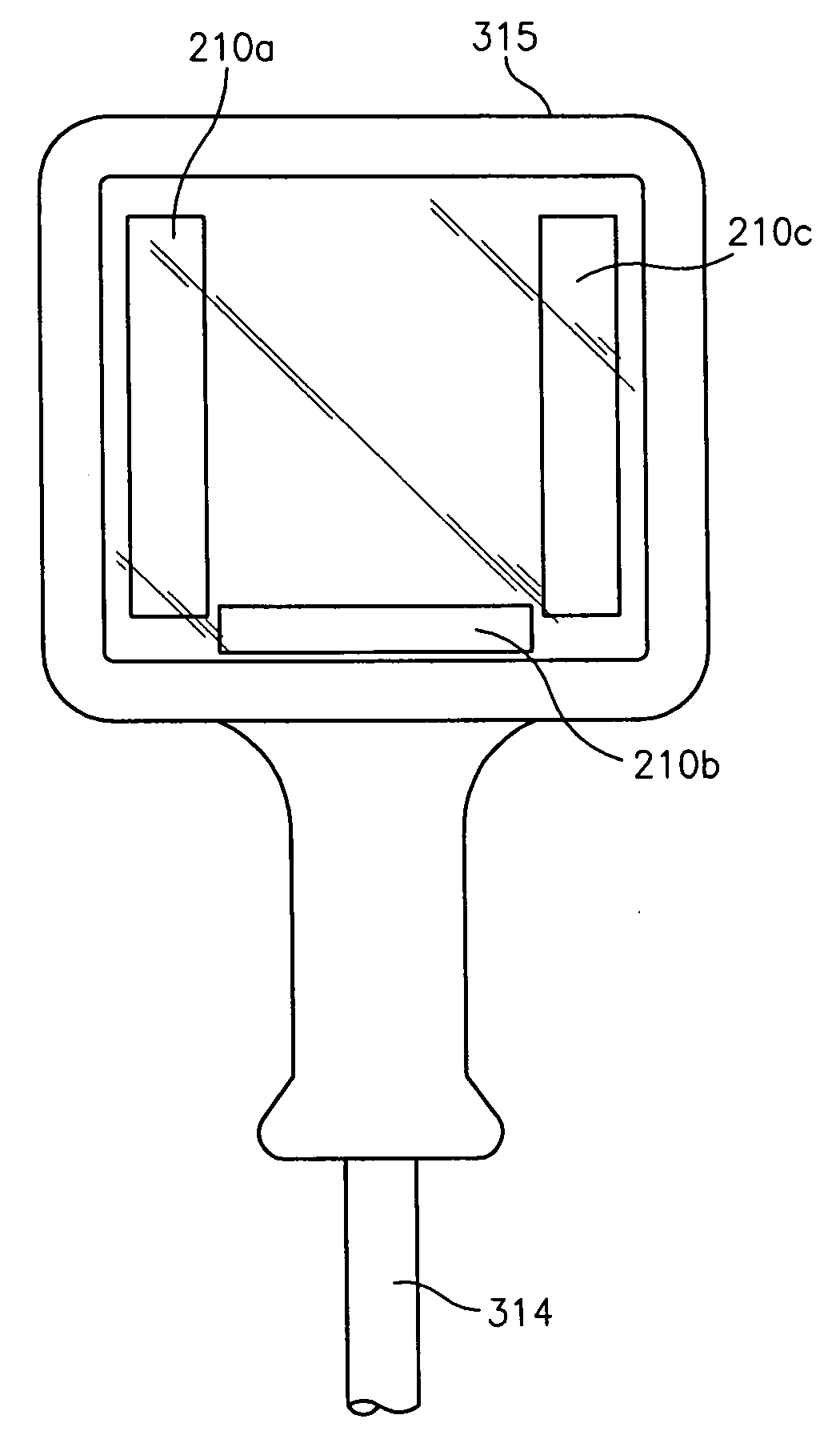
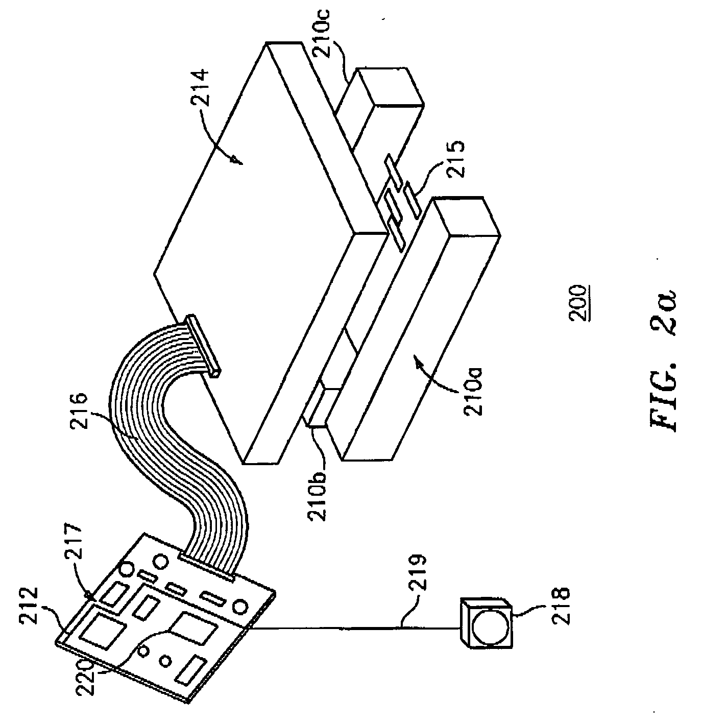
[0016] A system and method for reading and decoding optical codes using multiple color illumination is herein disclosed which achieves these and other aspects of the present invention. The system and method of the present invention utilize a color image sensor, such as CCD or CMOS color image sensor, enabling simultaneous acquisition of three monochrome images each having a different color, such as, for example, a red-colored image, a green-colored image, and a blue-colored image, as one superimposed, integrated image (i.e., one image frame). Each monochrome image of the integrated image corresponds to a DPM code or any other type of optical code. Each monochrome image is acquired by the image sensor after being illuminated by three different color light sources. The three different color light sources are provided in three corresponding banks of LEDs and oriented for providing simultaneous illumination from three different illumination directions. Each illumination direction corresponds to one of the three color light sources. The three monochrome images corresponding to each of the three banks of LEDs are acquired simultaneously as an integrated image by the image sensor, thereby decreasing overall image acquisition time by at least 66% compared to prior art direct part mark imaging systems.

Problems solved by technology

However, for many applications, such tags or labels may be lost, damaged or altered, thereby, rendering the coding useless.
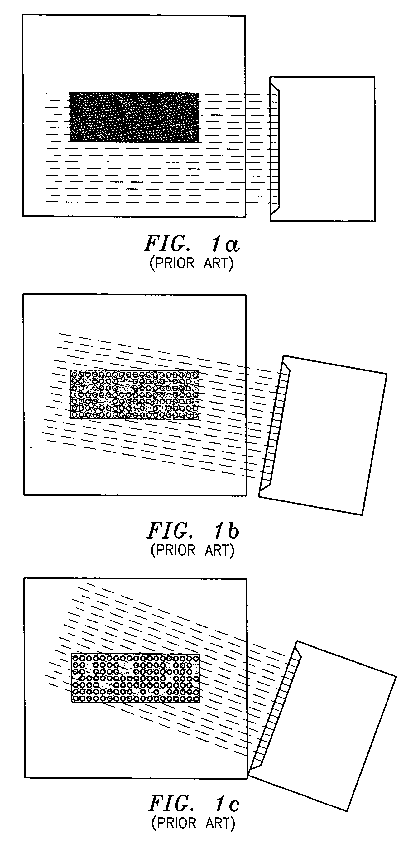
However, as a result of being etched directly onto a wide variety of material surfaces and textures, such as reflective or dark surfaces, properly illuminating, reading (and subsequently decoding) DPM codes is typically not possible with conventional code reading systems.
Therefore, DPM codes often have low and inconsistent contrast resulting in low code readability, and subsequently, many misreads or no reads.
The long acquisition time is mainly due to prior art imagers using a light source capable of illuminating using a single color or relying on ambient light for illumination.
Hence, prior art imagers can only image a DPM code from one illumination direction at a time.

Method used


Image

  • System and method for reading and decoding optical codes using multiple color illumination
  • System and method for reading and decoding optical codes using multiple color illumination
  • System and method for reading and decoding optical codes using multiple color illumination

Examples


Embodiment Construction

[0031] The present invention is suited for reading and decoding optical codes using multiple color illumination. The invention is particularly designed for imaging, reading and decoding DPM codes corresponding to a wide range of standardized 1-D and 2-D symbologies and even 3-D (multi-color) symbologies by incorporating the corresponding decoding and code identification algorithms for each code symbology within a logic board configured for providing image processing and decoding as known in the art and as discussed in further detail below. Accordingly, the present invention is discussed with a particular emphasis on imaging, reading and decoding DPM codes, even though the systems and methods of the present invention can be used to image and decode non-DPM codes.

[0032] The present invention provides a system and method that utilize a color image sensor, such as a CCD or CMOS color image sensor, enabling simultaneous acquisition of three monochrome images each having a different colo...


PUM


Abstract

An optical code reading system and method are provided for reading and decoding an optical code. The system includes a plurality of light sources, a color image sensor, a processor and a decoder. Each light source produces a unique wavelength / color of light to illuminate the optical code, such as a direct mark optical code. The image sensor detects the reflected light from the optical code and generates an integrated multi-colored image. The processor separates the integrated image into individual color channels, where each color channel includes data representative of the imaged optical code in one color. The processor analyzes the contrast for each color channel and determines which color channel has the optimum contrast. The data corresponding to the color channel having the optimum contrast is then decoded by a decoder.

Description

BACKGROUND OF THE INVENTION [0001] 1 Field of the Invention [0002] This invention relates to imaging using optical code reading devices. In particular, this invention relates to a system and method for reading and decoding optical codes using multiple color illumination. [0003] 2 Description of the Prior Art [0004] As industry has continued to refine and improve production techniques and procedures, corresponding requirements have been levied for placing identifying data related markings upon components of manufactured assemblies. These markings enable tracking of, for example, the historical stages of a product's manufacture. Further, these markings enable components of complex machinery, such as automobiles and the like, to be identified, for example, during manufacture by quality control personnel, during the course of an investigation by governmental authorities, etc. [0005] A variety of product marking approaches has been utilized in industry. For example, paper tags or labels ...

Claims


Application Information

Patent Timeline
Patent Type & Authority Applications(United States)
IPC IPC(8): G06K7/10
CPCG06K7/10851G06K7/10732
Inventor CARLSON, BRADLEY S.
Owner SYMBOL TECH LLC
Learn More