Detection assembly and measuring arrangement for multigas analyzers

Active Publication Date: 2005-01-20
INSTRUMENTARIUM CORP
View PDF8 Cites 15 Cited by
  • Summary
  • Abstract
  • Description
  • Claims
  • Application Information

AI Technical Summary

Benefits of technology

[0017] The object of this invention is to provide a compact and lightweight detection assembly and measuring arrangement for a multigas NDIR analyzer and to minimize its sensitivity to the contamination of the measuring chamber. Another object of the invention is to provide a compact and lightweight detection assembly and measuring arrangement without moving mechanical parts. A third object of the invention is to provide a detection assembly to a multigas NDIR analyzer so that its optical construc

Problems solved by technology

It is not possible to zero a clinical gas analyzer of the mainstream type because the measuring chamber is all the time located in the patient's breathing circuits, whereupon it is not possible to fill the measuring chamber with zero gas.
Because the measuring chamber is on the breathing circuit, it is easily contaminated by mucus or condensed water.
It is not possible to zero it during its normal operation.
Due to these requirements, only single gas analyzers for carbon dioxide CO2 have been available and no multigas analyzers of the mainstream type have been commercially available.
The optical and mechanical construction of a dual path analyzer is quite complicated.
Problems caused by the contamination of the measuring chamber cannot be solved by the dual path construction.
Thus, the dual path construction is generally not used in mainstream gas analyzers.
This makes the analyzer sensitive to the contamination of the measuring chamber.
The drawback of the beam splitter construction is that the beam splitter decreas

Method used


Image

  • Detection assembly and measuring arrangement for multigas analyzers
  • Detection assembly and measuring arrangement for multigas analyzers
  • Detection assembly and measuring arrangement for multigas analyzers

Examples


Embodiment Construction

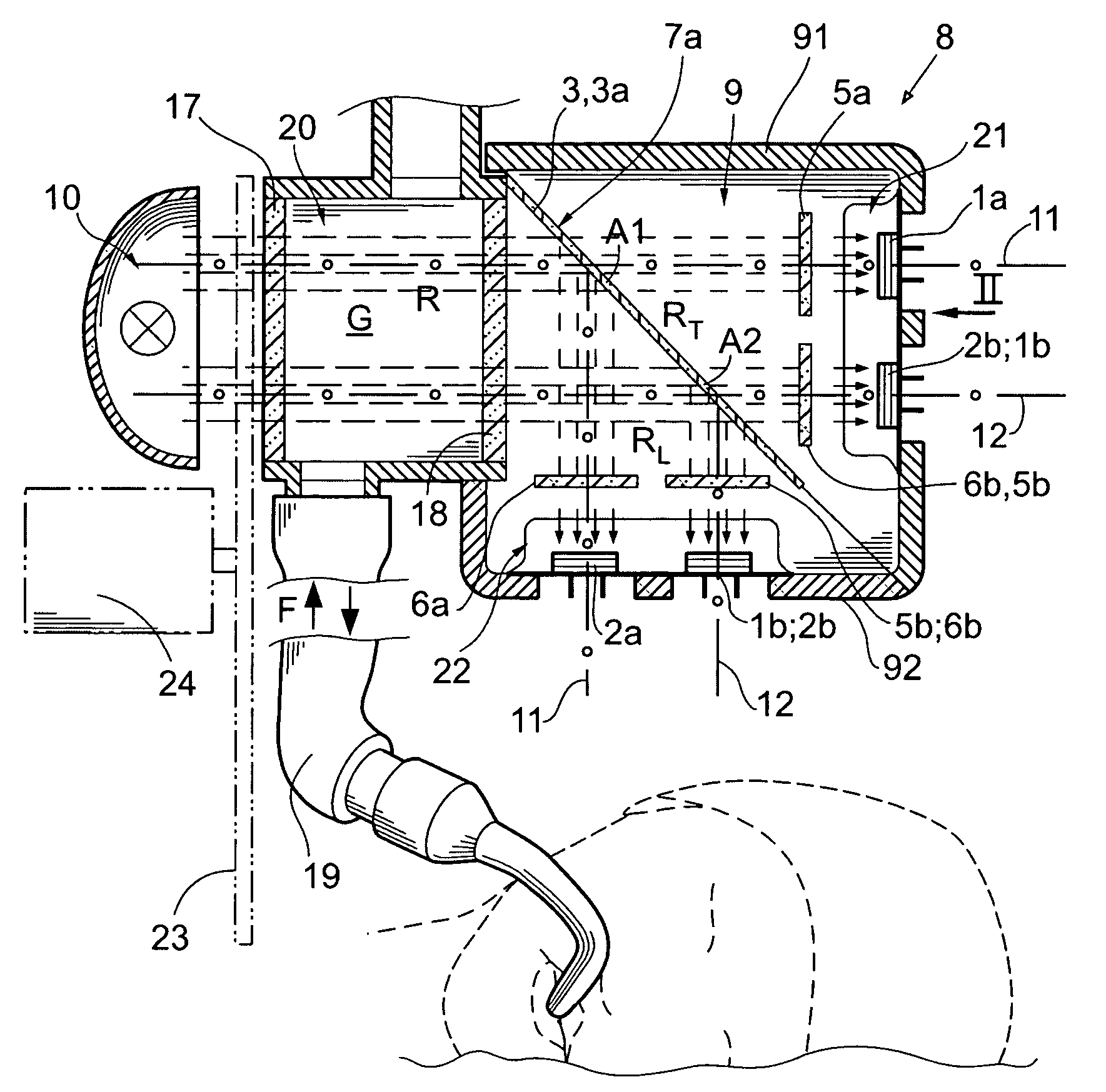
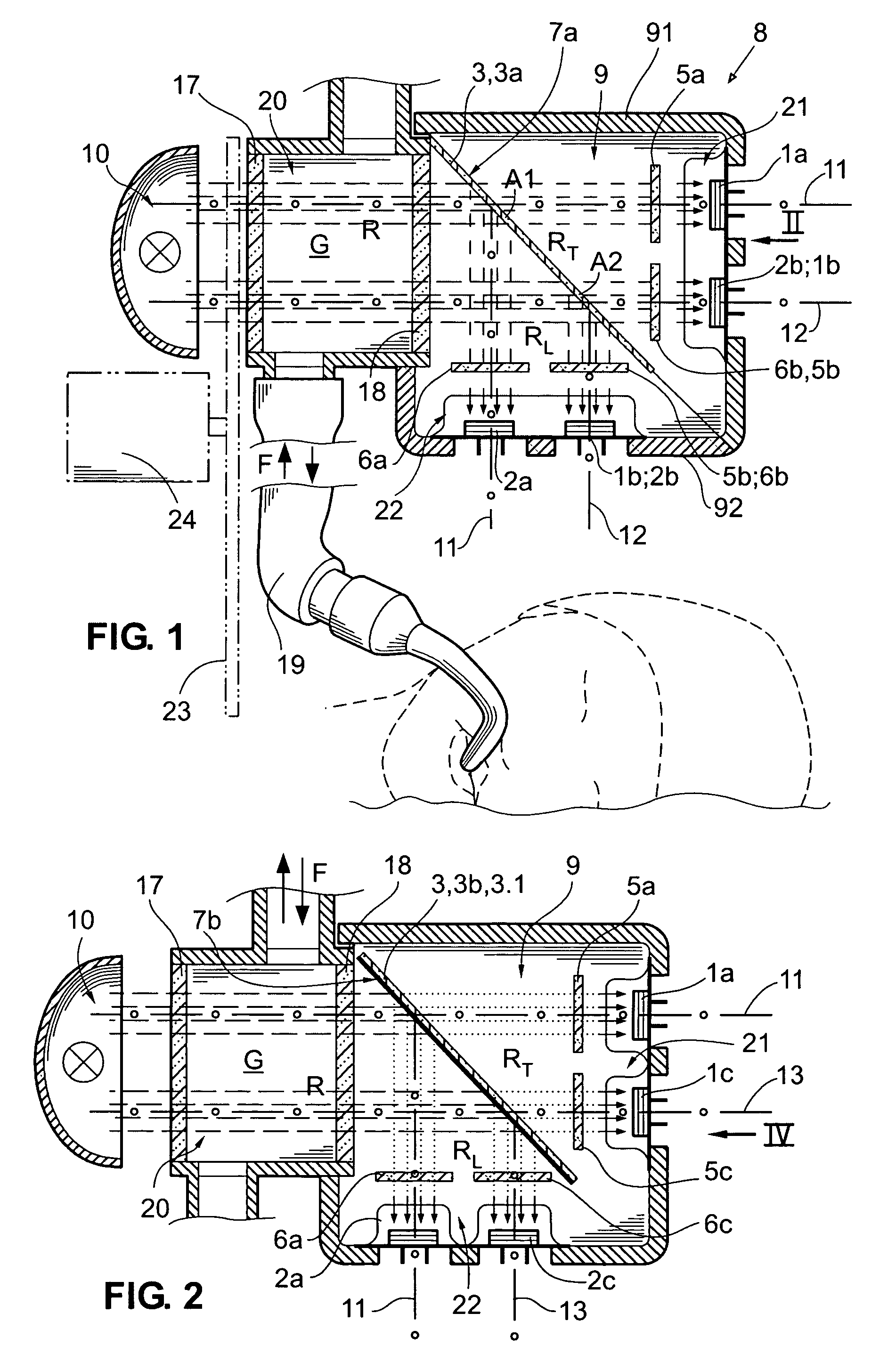
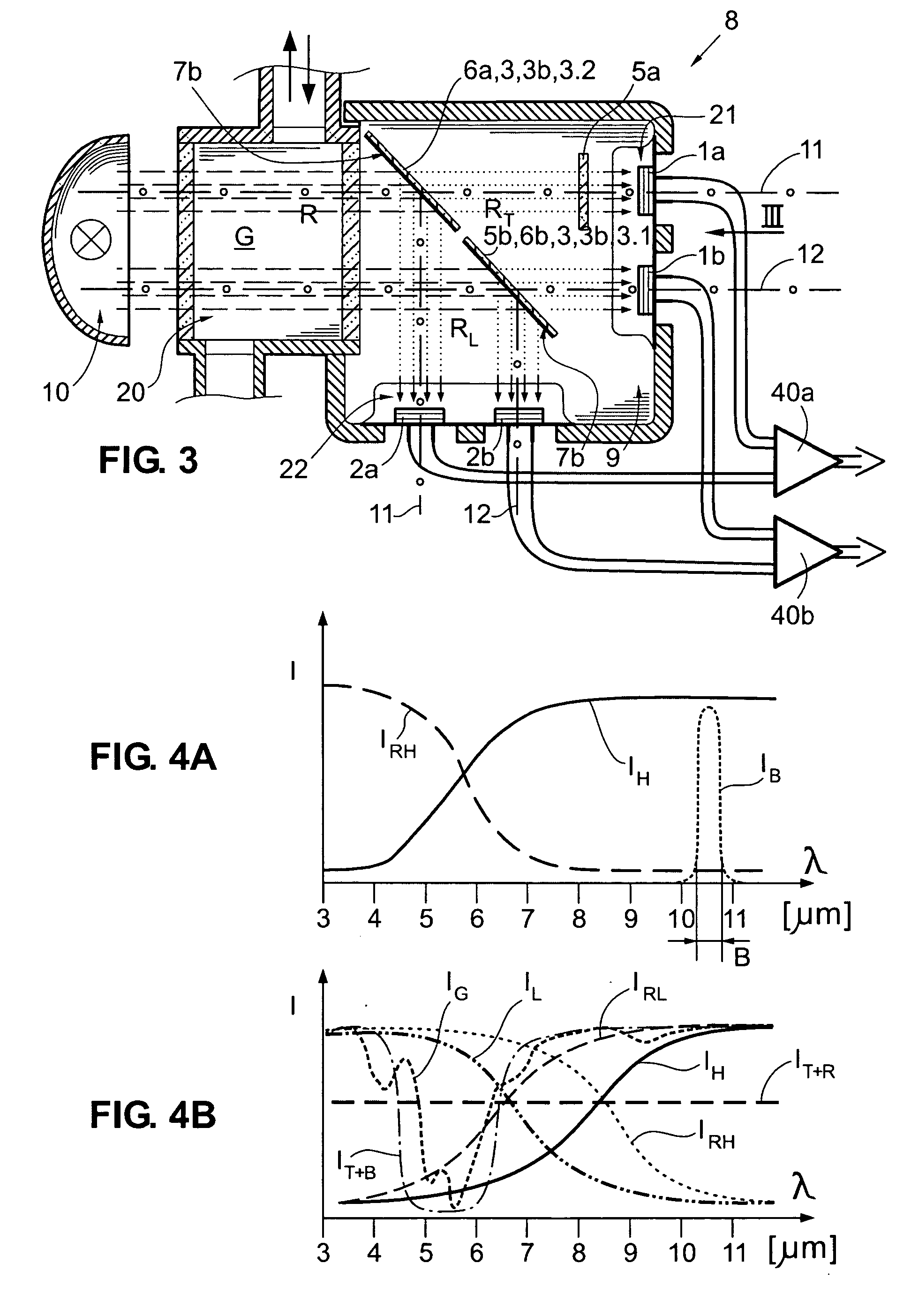
[0035] In the following FIGS. 1 to 3 and 5 to 6B, the detection assembly 9 and measuring arrangement 8 according to the invention is represented for two measurement and reference channels, i.e. two independent single path analyzer channels 11, 12 for simplicity and legibility of the drawings. The first independent single path analyzer channel 11 have a true single beam or beam section through the measuring chamber, as do the second single path analyzer channel 12. In the FIG. 6C there is shown four independent single path analyzer channels 11 to 14 of the detection assembly 9, but not all parts of the measuring arrangement 8. It shall be understood that those parts of the measuring arrangement not shown are similar or analogous to the respective parts of the two channel embodiments shown in FIGS. 1 to 3 and 5 to 6B. The present invention employs detector units 21, 22, 23, 24 etc. within the detection assembly 9, each detector unit having at least a first detector 1a, 1b, 1c . . . an...


PUM


Abstract

A non-dispersive infrared measuring arrangement for a multigas analyzer is described having a radiation source (10), a measuring chamber (20), a beam splitter (3), at least a first and a second detector unit (21, 22) both with at least two detectors (1a, 1b; 2a, 2b); and optical filters in radiation beam portions ending in said detectors. The detector units receive the reflected beam portions (RR) and the transmitted beam portion (RT). Both the first and second detector units (21, 22) have: at least one measuring detectors (1a, 1b) provided with an optical measurement filter (5a, 5b); and at least one reference detectors (2a, 2b) provided with an optical reference filter (6a, 6b). Alternatively, the first detector unit (21) has at least two measuring detectors (1a, 1b) each provided with an optical measurement filter (5a, 5b), and the second detector unit (22) has at least two reference detectors (2a, 2b) each provided with an optical reference filter (6a, 6b). The first detector in said first detector unit and said second detector in said second detector unit are positioned to constitute a first independent single path analyzer channel (11), and said second detector in said first detector unit and said first detector in said second detector unit are positioned to constitute a second independent single path analyzer channel (12).

Description

FIELD OF THE INVENTION [0001] The present invention relates to infrared multigas analyzers that measure concentrations of the desired gas components in the gas sample and may also identify the presence of some gas components. More specifically, the present invention relates to a detection assembly for a non-dispersive infrared multigas analyzer, comprising: a beam splitter for dividing an IR-radiation beam into at least one reflected beam portion and at least one transmitted beam portion, at least a first and a second detector unit both with at least two separate detectors respectively, and optical filters in front of said detectors; said detector units being positioned to receive said at least one reflected beam portion and said at least one transmitted beam portion respectively. The present invention also relates to a non-dispersive infrared measuring arrangement in a multigas analyzer, comprising: a radiation source providing an IR-radiation beam; a measuring chamber for receivin...

Claims


Application Information

Patent Timeline
IPC IPC(8): G01N21/35G01N21/61
CPCG01N21/61G01N21/3504
Inventor WECKSTROM, KURTKARLSSON, KAI
Owner INSTRUMENTARIUM CORP
Why Eureka
Try Eureka