

Synthesizer
a technology of synthesizer and output clock, which is applied in the field of synthesizer, can solve the problems of inability to partition the period of the output clock signal to be switched, inability to switch the frequency of the output clock signal at a high speed, and inability to switch the frequency of the output clock signal in a broad band
- Summary
- Abstract
- Description
- Claims
- Application Information
AI Technical Summary
Benefits of technology
Problems solved by technology
Method used
Image

Examples
embodiment 1
[0095] Embodiment 1
[0096] An embodiment 1 of the present invention will be explained in details, by making a reference to the accompanied drawings.
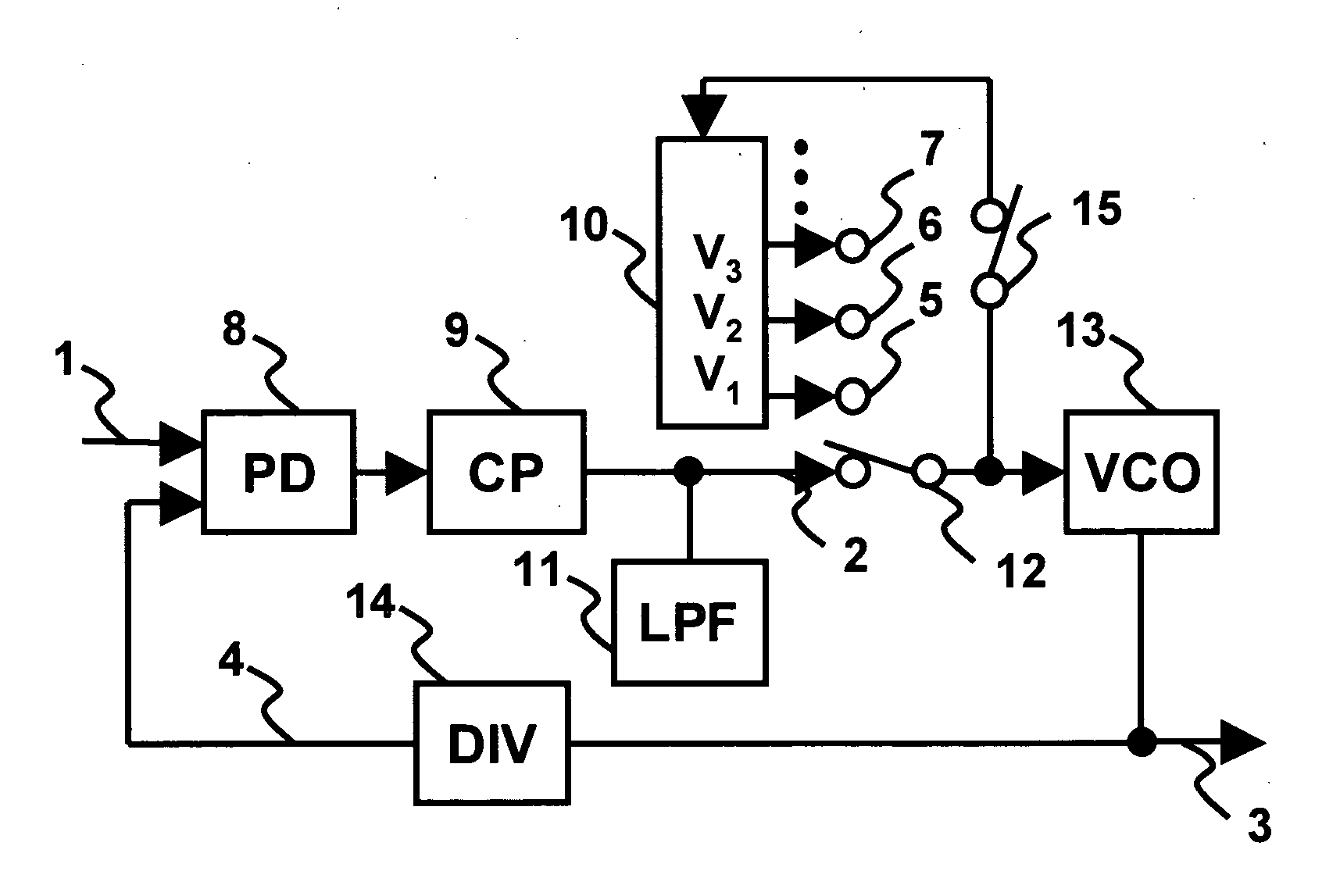
[0097]FIG. 1 is a block diagram illustrating the embodiment 1 of the present invention.
[0098] As shown in FIG. 1, the synthesizer of the embodiment 1 of the present invention has a phase detector 8 and a charge pump circuit 9 for injecting an electric charge, or pulling it out that corresponded to a frequency difference between an input clock signal 1 and an output signal 4 of the divider, a low-pass filter 11 for converting this electric charge into a voltage, a voltage control oscillator (VCO) 13 for changing an output frequency for this voltage, a divider 14 for dividing the frequency of the input, a voltage holding circuit 10 for holding the input voltage that corresponds to a plurality of output frequencies of the VCO 13, a low-pass filter 11, and a switch 12 for switching the holding voltage of the voltage holding circuit 10.
[009...
embodiment 2
[0116] Embodiment 2
[0117] An embodiment 2 of the present invention will be explained in details, by making a reference to the accompanied drawings.
[0118]FIG. 6 is a block diagram illustrating the synthesizer in the embodiment 2 of the present invention.
[0119] As shown in FIG. 6, as compared with the embodiment 1, the synthesizer of the embodiment 2 differs in having a current control oscillator 44 instead of the VCO 13, a current holding circuit 42 instead of the voltage holding circuit 10, and further a voltage / current converter 41 for converting the output signal of the low-pass filter into a current. Additionally, a phase detector 38, a charge pump circuit 39, a low-pass filter 40, and a divider 45 have a configuration similar to the phase detector 8, the charge pump circuit 9, the low-pass filter 11, and the divider 14 in the embodiment 1, whereby detailed explanation thereof is omitted.
[0120] Next, the operation of the embodiment 2 will be explained, by making a reference to...
embodiment 3
[0123] Embodiment 3
[0124] An embodiment 3 of the present invention will be explained in details, by making a reference to the accompanied drawings.
[0125]FIG. 7 is a block diagram illustrating a circuit configuration of the embodiment 3 of the present invention.
[0126] As shown in FIG. 7, as compared with the embodiment 1, the embodiment 3 differs in having no holding voltage circuit 10, and having a first low-pass filter 82 and a second low-pass filter 83, and a switch 86 for switching these. The number of the low-pass filter may be plural.
[0127] Additionally, a phase detector 93, a charge pump circuit 94, a VCO 88, and a divider 95 have a configuration similar to the phase detector 8, the charge pump circuit 9, the VCO 13, and the divider 14 in the embodiment 1, whereby detailed explanation thereof is omitted.
[0128] Next, the operation of this embodiment will be explained, by making a reference to the accompanied drawings.
[0129] As shown in FIG. 7, by making a switchover betwee...
PUM
 Abstract
Description
Claims
Application Information