
Local area network of serial intelligent cells

a technology of intelligent cells and local area networks, applied in data switching networks, power distribution line transmission, powerline communications applications, etc., can solve problems such as the absence of media in electrically-conducting media

Inactive Publication Date: 2005-01-20
CONVERSANT INTPROP MANAGEMENT INC
View PDF99 Cites 14 Cited by
  • Summary
  • Abstract
  • Description
  • Claims
  • Application Information

AI Technical Summary

Benefits of technology

[0039] As noted above, SIC's in a communicating pair communicate bidirectionally. For example, SIC 704 can initiate communication (as a sender) to SIC 702 (as a receiver), but SIC 704 can just as well initiate simultaneous communication (as a sender) to SIC 700 (as a receiver). Bidirectional communication can take place simultaneously, and herein is taken to be equivalent to “full duplex” communication. In addition, as noted above, the communication between the SIC's of a communicating pair is independent of the communication between the SIC's of any other communicating pair, in that these communications neither preclude nor affect one another in any way. Furthermore, every communication between SIC's is a “point-to-point communication”, which term herein denotes a communication that takes place between exactly one sender and exactly one receiver. This is in contrast to a bus-based communication, in which there are many (potential) receivers and many (potential) senders. Consequently, in the topology according to the present invention, there is automatically a termination in the physical layer at each end of a connection (a SIC), both simplifying the installation and insuring more reliable communication.
[0042] 2. Point-to-point communication allows higher data rates over greater distances.
[0047] 7. In the case of failure of any conductor or SIC, the network can sense the fault immediately, and the specific location of the fault (up to the specific SIC pair) is easily obtained.

Problems solved by technology

But electrically-conducting media do not include media such as fiber optic lines, waveguides, microwave, radio, and infrared communication media.

Method used


Image

  • Local area network of serial intelligent cells
  • Local area network of serial intelligent cells
  • Local area network of serial intelligent cells

Examples


Embodiment Construction

[0060] The principles and operation of a local area network according to the present invention may be better understood with reference to the drawings and the accompanying description.

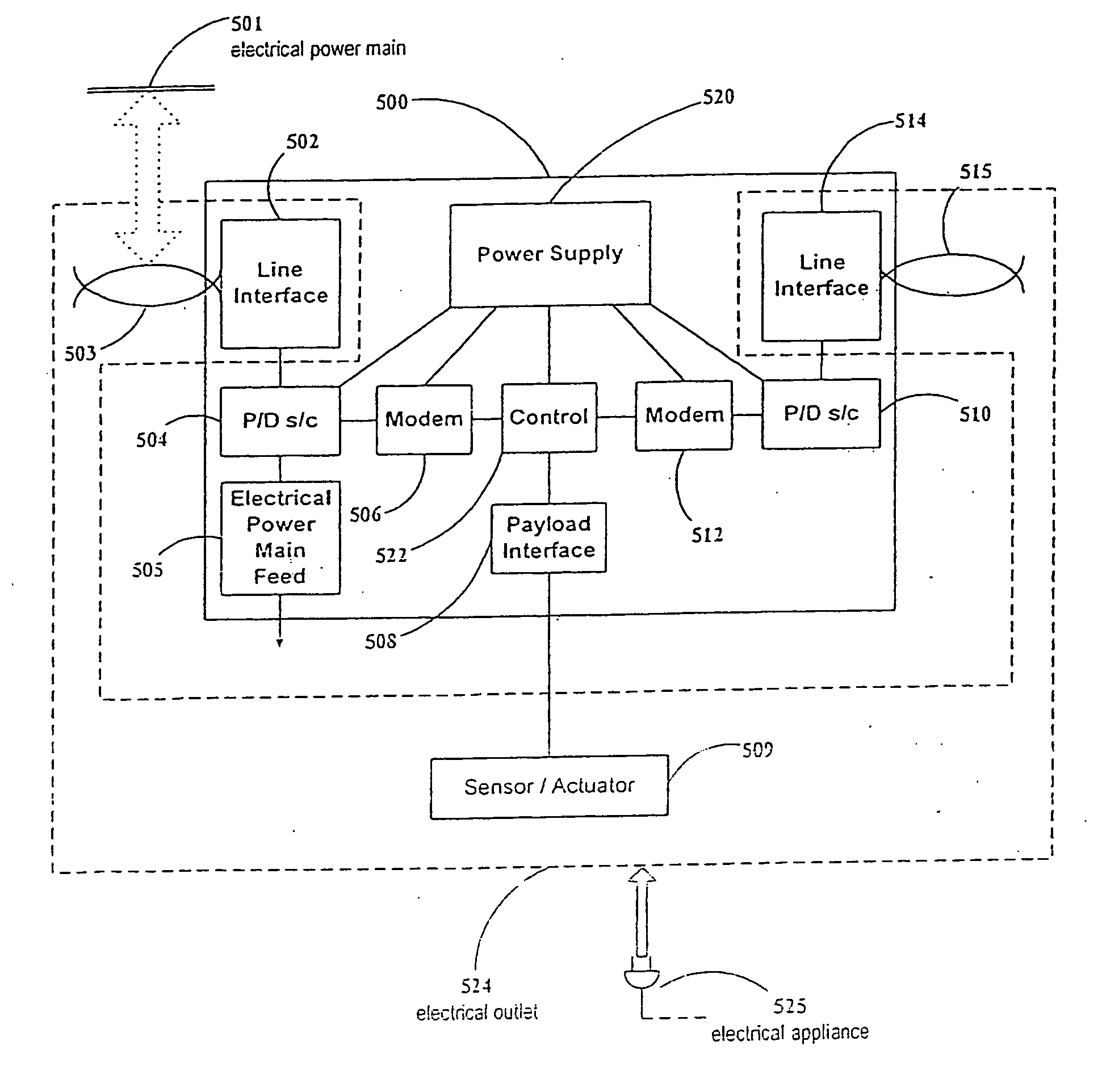
[0061]FIG. 5 is a block diagram of a representative SIC 500 for use in control applications. A first line interface 502 is a first port for connecting to the previous SIC to receive incoming electrical power and local area network data over electrically-conducting medium 503, which may optionally be connected to an electrical power main 501, so that SIC 500 may be powered from electrical power main 501. Line interface 502 may include the connector, fuse, lightning arrester and other protection such as noise filters, etc. The incoming power / data signal is fed to a first power / data splitter / combiner 504, which de-couples the (high frequency alternating current) data signal from the power. Such a power / data splitter / combiner 504 (denoted for brevity in FIG. 5 as “P / D s / c”) can be implemented by methods w...


PUM


Abstract

A device for coupling first and second bi-directional wired digital data signals to each other and to a data unit, for use with first and second service wire pairs installed at least in part in walls within a building. The first service wire pair concurrently carries the first bi-directional wired digital data signal and a first service signal carried over a first service signal frequency band, using frequency division multiplexing. The first wired digital data signal is carried over a frequency band distinct from the first service signal frequency band. The second service wire pair concurrently carries a second bi-directional wired digital data signal and a second service signal carried over a second service signal frequency band, using frequency division multiplexing. The second wired digital data signal is carried over a frequency band distinct from the second service signal frequency band.

Description

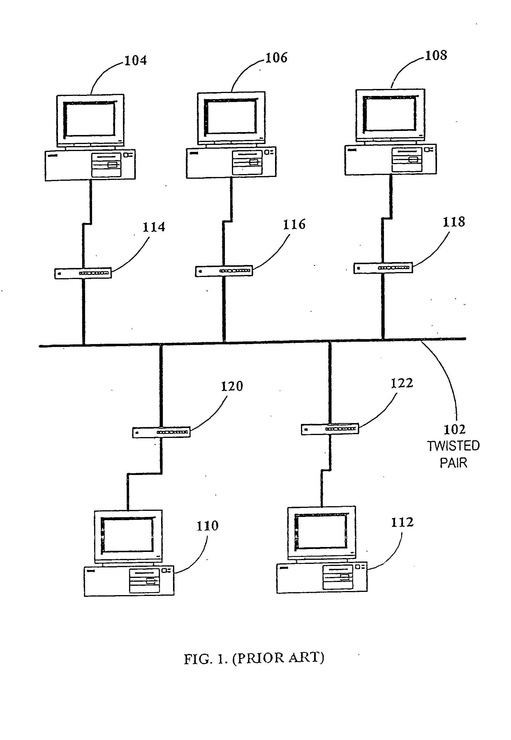
[0001] This is a continuation of copending parent application Ser. No. 10 / 178,223, filed Jun. 25, 2002, which itself is a continuation of U.S. patent application Ser. No. 09 / 123,486 filed Jul. 28, 1998, now U.S. Pat. No. 6,480,510, issued Nov. 12, 2002.FIELD AND BACKGROUND OF THE INVENTION [0002] The present invention relates to local area networks and, more particularly, to local area network topologies based on serial intelligent cells. [0003] Bus Topology [0004] Most prior art local area networks (LAN) use a bus topology as shown by example in FIG. 1. A communication medium 102 is based on two conductors (usually twisted pair or coaxial cable), to which data terminal equipment (DTE) units 104, 106, 108, 110, and 112 are connected, via respective network adapters 114, 116, 118, 120, and 122. A network adapter can be stand-alone or housed within the respective DTE. [0005] This prior art bus topology suffers from the following drawbacks: [0006] 1. From the point of view of data comm...

Claims


Application Information

Patent Timeline
Patent Type & Authority Applications(United States)
IPC IPC(8): H04B3/54H04J99/00H04L12/28H04L12/46H04L29/06
CPCH04B3/54H04L12/2602H04B2203/5437H04B2203/5445H04B2203/545H04B2203/5458H04L12/2801H04L12/2803H04L12/2838H04L29/0602H04L2012/2843H04L2012/2845H04M19/02Y10S370/908H04L5/14H04B3/542H04L43/00H04L67/00H04L12/42
Inventor BINDER, YEHUDA
Owner CONVERSANT INTPROP MANAGEMENT INC
Learn More