
System and method for measuring a high speed signal

Active Publication Date: 2005-01-20
MARVELL ASIA PTE LTD
View PDF5 Cites 11 Cited by
  • Summary
  • Abstract
  • Description
  • Claims
  • Application Information

AI Technical Summary

Benefits of technology

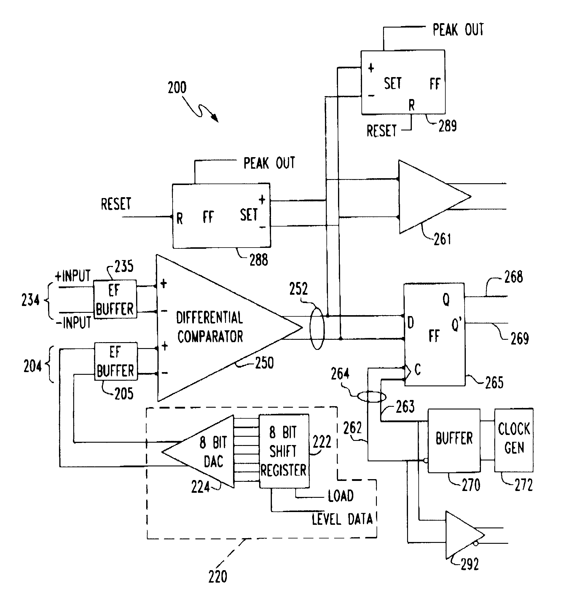
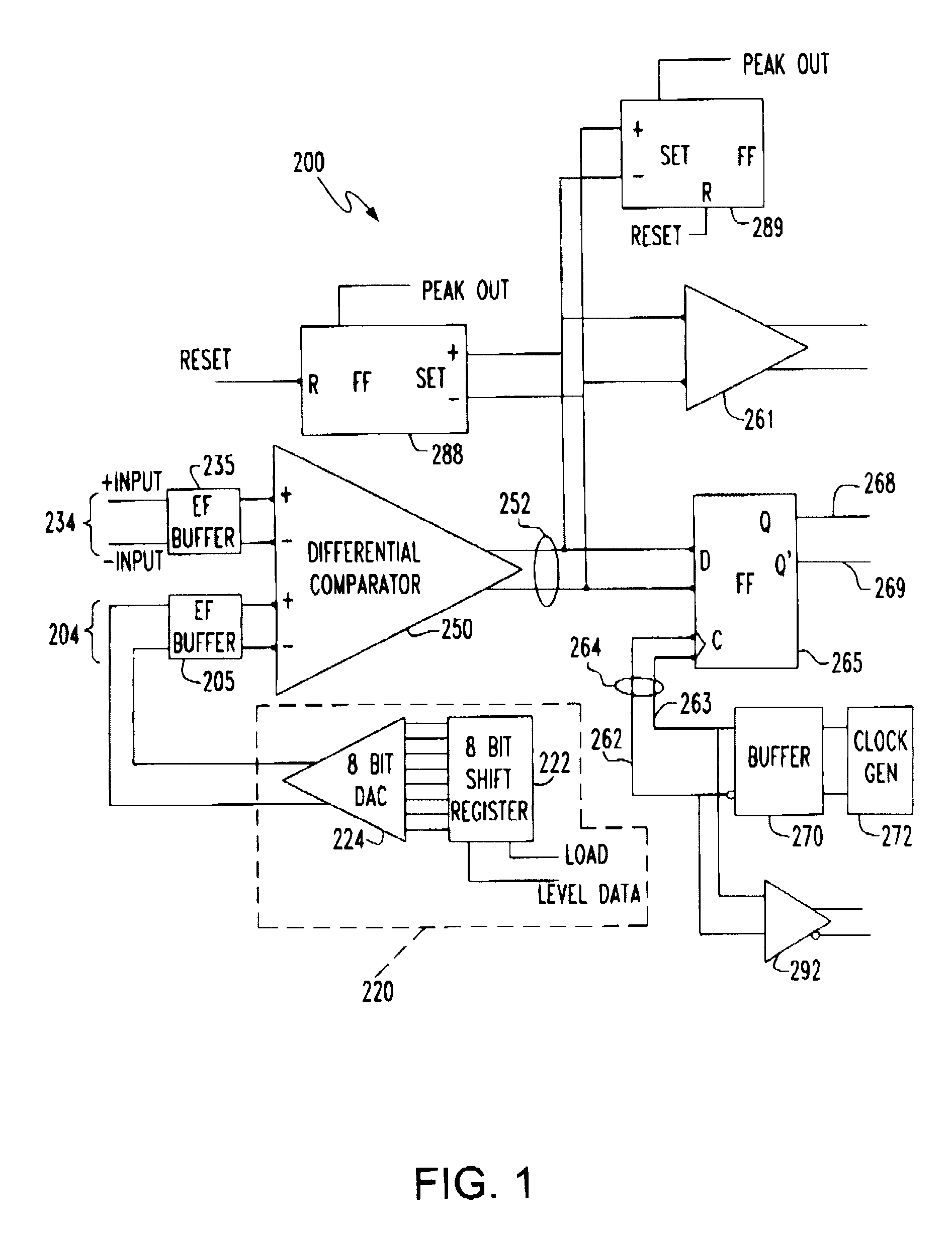
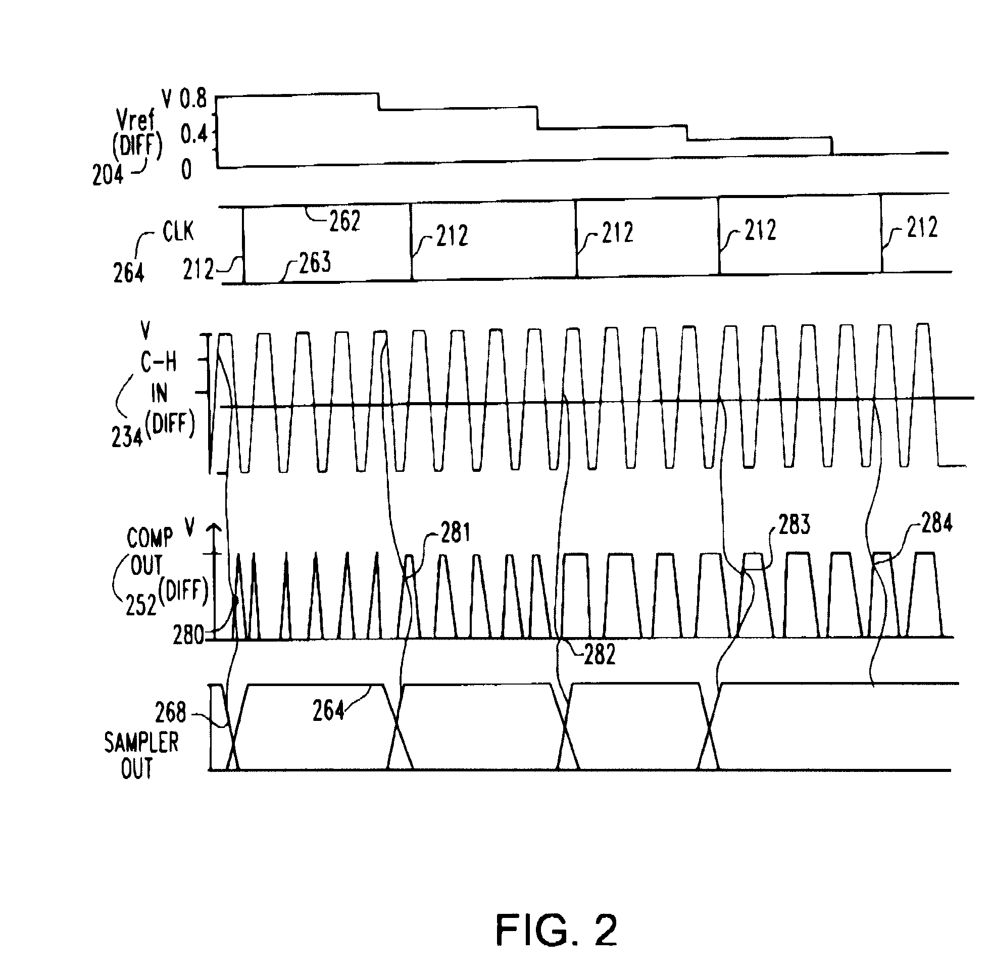
[0007] According to an aspect of the invention, an apparatus is provided for measuring an output of a high-speed data transmission circuit. The apparatus includes a programmable reference voltage generator operable to generate a reference voltage that is variable between a plurality of levels. The apparatus also includes a quantizer to quantize an output of the high-speed data transmission circuit relative to the referenc

Problems solved by technology

As the level of integration of chips has increased, however, the difficulty of testing them has also increased.
A number of methods are used to test the operation of chips after fabrication, but many of them are ineffective to test parameters of high-speed operation.
However, the testing of a high-speed serial data transmitter presents challenges that cannot be satisfactorily addressed by the above method.
In such testing method, the probes, socket, wiring, and printed circuit board between the chip and external test equipment have high inductance and parasitic capacitance, which limits the bandwidth of signals that can reach the test equipment.
Therefore, signal characteristics of the high-speed outputs cannot be measured using only the available post-fabrication test fixtures and test equipment.
An output signal having an eye width or eye height outside of tolerances can cause the bit error rate for receiving the transmitted output signal to exceed threshold.
However, since the output signals of such high-speed serial data transmitters are outside of the bandwidth of the available test fixtures and equipment, a new system and method are needed to measure the output signal characteristics.

Method used


Image

  • System and method for measuring a high speed signal
  • System and method for measuring a high speed signal
  • System and method for measuring a high speed signal

Examples


Embodiment Construction

[0012] Accordingly, an objective of the invention is to provide a system and method for measuring a high-speed signal which are compatible with existing types of production test fixtures and equipment, such that characteristics of the high-speed signal can be determined. When the invention is implemented on a chip including a high-speed serial data transmitter, the characteristics of the high-speed signal output by the chip can be measured and analyzed through an interface to a production test fixture and equipment.

[0013] The system of the invention is primarily intended to be implemented on the same chip that includes a high-speed serial data transmitter. The measurement system of the invention requires a high bandwidth, low loss environment that is often best obtained on the same chip on which the high-speed serial transmitter is located, due to bandwidth limitations and losses that occur external to the chip. In such way, characteristics of the high-speed signal can be measured ...


PUM


Abstract

An apparatus is provided for measuring an output of a high-speed data transmission circuit. The apparatus includes a programmable reference voltage generator operable to generate a reference voltage that is variable between a plurality of levels. The apparatus also includes a quantizer to quantize an output of the high-speed data transmission circuit relative to the reference voltage level input thereto. Also included is a clock generator operable to generate a clock having a transitioning time (rise-time, fall-time or both) that is less than one quarter of a minimum switching period of the output of the circuit. Finally, the apparatus includes a sampler operable to sample the quantized output with the clock to produce a plurality of samples which measure the output of the circuit.

Description

BACKGROUND OF INVENTION [0001] The invention relates generally to the measurement of an electronically transmitted signal, and more particularly to a system and method for measuring a high-speed signal, such as a signal of an integrated circuit. [0002] After an integrated circuit (“IC”, or “chip”) has been designed and fabricated, it is tested to determine whether the chip functions as intended. As the level of integration of chips has increased, however, the difficulty of testing them has also increased. [0003] A number of methods are used to test the operation of chips after fabrication, but many of them are ineffective to test parameters of high-speed operation. For example, in frequently used methods, a fixture having a socket outfitted with probes contacts the bond pads of a chip or a chip module. A set of signal lines connect the socket of the fixture to test equipment. When the chip or module is so connected to test equipment, basic functional operation of the chip is then ve...

Claims


Application Information

Patent Timeline
IPC IPC(8): H04B17/00
CPCH04B17/18
Inventor SMITH, THOMAS J.SORNA, MICHAEL A.SWEENEY, JOHN F.
Owner MARVELL ASIA PTE LTD
Learn More