Clockless transmission system and clockless transmission method

Active Publication Date: 2010-02-18
NEC CORP
View PDF3 Cites 38 Cited by
  • Summary
  • Abstract
  • Description
  • Claims
  • Application Information

AI Technical Summary

Benefits of technology

[0044]According to the invention, because the clockless transmission system has high noise tolerance, although power supply noise or the like is generated due to the operation of the disp

Problems solved by technology

However, the RSDS has a problem in that, because impedance mismatching occurs at the bus-connected transmission paths, the transmission speed is limited by multi-reflection of signals.
In addition, the Mini-LVDS has a problem in that the transmission speed is limited by the skew of the clock signal and the data signal that run parallel.
Thus, in case of using such transmission methods, the number of channels should be increased for a large capacity, inevitably resulting in an increase in the costs of a transmission medium due to multi-layered substrate or the like.
At this time, display driving circuit 508 consumes much current in writing the pixel data, generating much power supply noise.
This brings about an error, when a front bit of pixel data to be written on the display is received, after the blanking interval ends.
However, patent document 1 does not disclose prevention of an error generated based on power supply noise in a clockless transmission system.
However, patent document 2 do

Method used


Image

  • Clockless transmission system and clockless transmission method
  • Clockless transmission system and clockless transmission method
  • Clockless transmission system and clockless transmission method

Examples


Embodiment Construction

[0051]Preferred exemplary embodiments of the present invention will now be described with reference to the accompanying drawings.

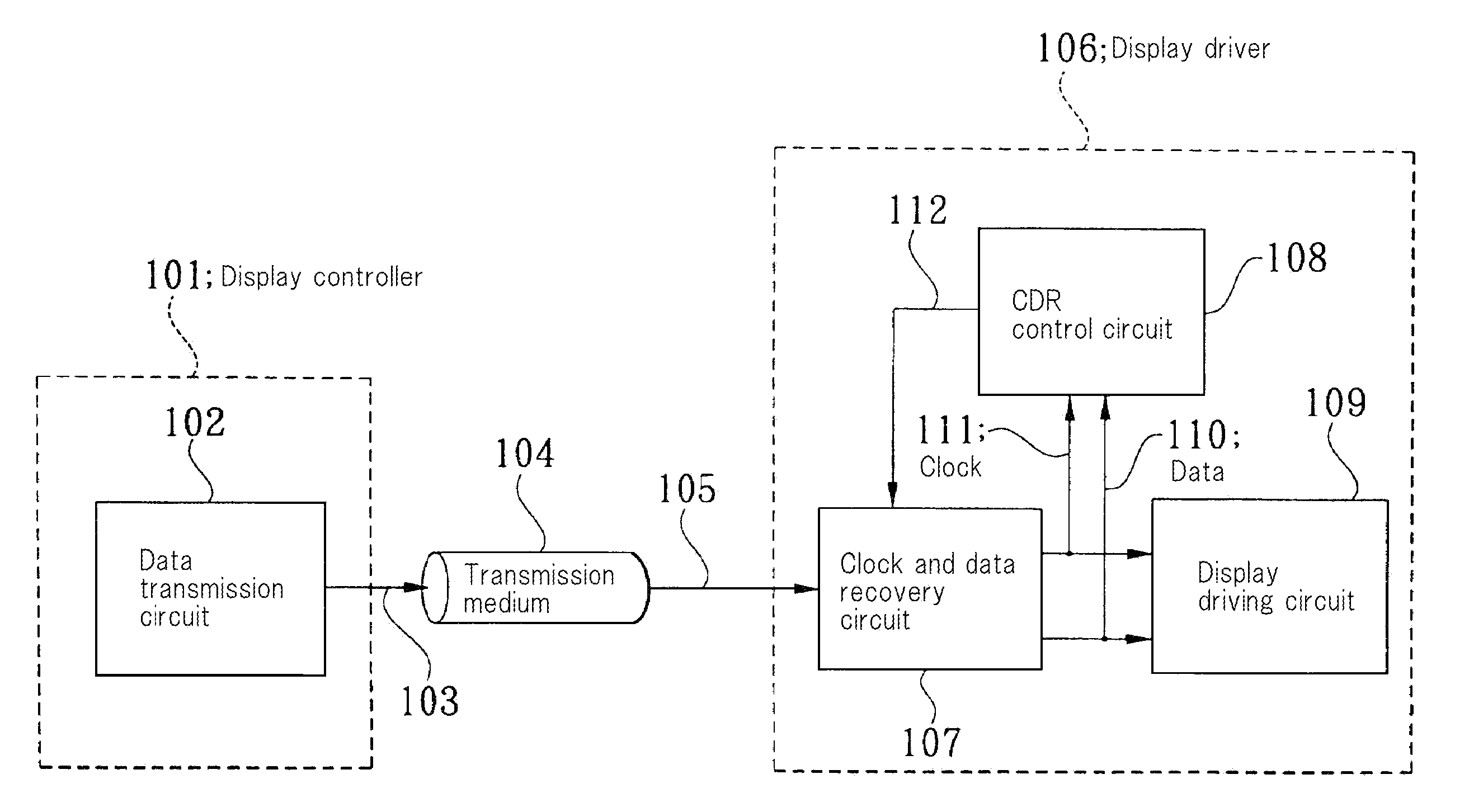
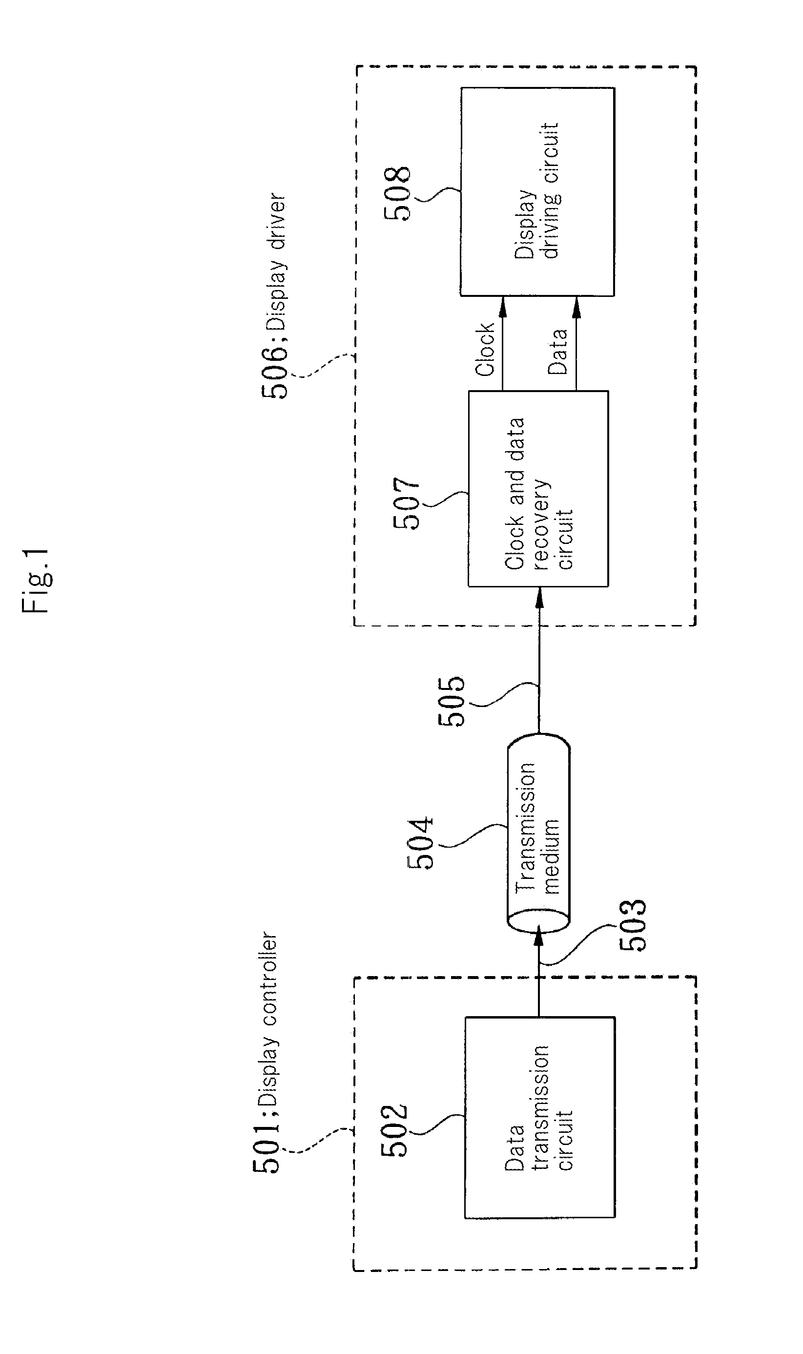
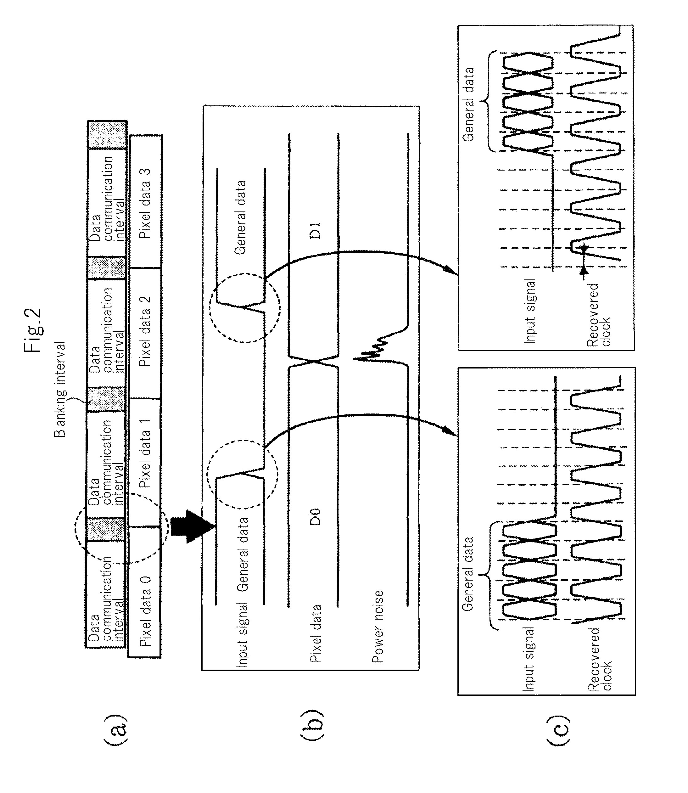
[0052]FIG. 3 is a block diagram showing the configuration of a clockless transmission system according to an exemplary embodiment of the present invention. FIG. 4 is a timing chart for explaining the operation of the clockless transmission system according to an exemplary embodiment of the present invention. FIG. 5 is a diagram showing closed loop characteristics of a clock and data recovery circuit according to an exemplary embodiment of the present invention. FIG. 6 is a diagram showing an eye representation of input signals of the clock and data recovery circuit according to an exemplary embodiment of the present invention.

[0053]As shown in FIG. 3, a clockless transmission system according to this exemplary embodiment includes display controller 101, transmission medium 104, and display driver 106. Display controller 101 includes data transmission circu...


PUM


Abstract

A clockless transmission system includes display controller 101 and display driver 106. Display controller 101 includes data transmission circuit 102 configured to output general data obtained by multiplexing a clock by coding serialized pixel data for each pixel data during a data communication interval and also to output a predetermined control signal during a blanking interval. Display driver 106 includes clock and data recovery circuit 107 configured to output the pixel data from the general data transferred from the display controller and to increase a loop gain of a feedback loop in clock recovery such that the loop gain is larger than that when the general data is received, according to control data of the control signal, to recover and output a clock, and display driving circuit 109 configured to output a signal for driving a display based on the pixel data and the recovered clock.

Description

TECHNICAL FIELD[0001]The present invention relates to a clockless transmission system and clockless transmission method capable of ensuring synchronization between a recovered clock in a clock and data recovery circuit and an input signal even in an environment in which much noise is generated such as when a display driving circuit or the like operates.BACKGROUND ART[0002]Recently, as flat panel displays are increased in size, the amount of data to be supplied to a display driver from a display controller increases. For example, for a UXGA (1920×1200) display, data need to be supplied to each pixel at the intervals of (1920+180)*(1200+300)*60 Hz=189 MHz (180 and 300 correspond to blanking intervals). Accordingly, the amount of data to be supplied to the display driver reaches 6.8 Gbit (189 MHz*12 bit*3(RGB)) per second.[0003]As a high speed interface (IF) technique for the display driver, RSDS (Reduced Swing Differential Signaling) or Mini-LVDS (Low Voltage Differential Signaling) h...

Claims


Application Information

Patent Timeline
IPC IPC(8): G06F1/04
CPCG09G3/2096G09G5/008H04L7/10H04L7/033H04L7/046H03L7/06
Inventor YAMAGUCHI, KOUICHI
Owner NEC CORP
Why Eureka
Try Eureka