
Micro fuel cell architecture

a fuel cell and micro-chip technology, applied in the field of fuel cell technology, can solve the problems of increasing the thickness, volume, and size of the fuel cell package, and reducing so as to facilitate conductive thermal communication and improve the thermal management of the fuel cell

Inactive Publication Date: 2005-01-20
ULTRACELL LLC
View PDF86 Cites 71 Cited by
  • Summary
  • Abstract
  • Description
  • Claims
  • Application Information

AI Technical Summary

Benefits of technology

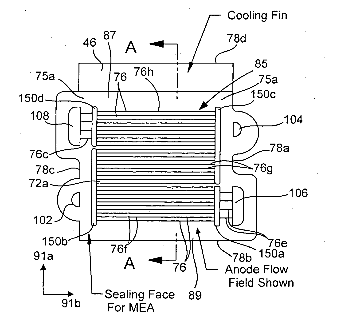
[0007] The present invention relates to fuel cells that generate electrical energy and components used within a fuel cell. One aspect of the invention improves fuel cell thermal management. In this case, a bi-polar plate included the fuel cell stack comprises one or more heat transfer appendages. Arranging an appendage on an external portion of the bi-polar plate permits conductive thermal communication between inner portions of the plate and the external appendage. The appendage thus enables external thermal regulation of internal portions of a fuel cell stack. The heat transfer appendage may be integrally formed with the bi-polar plate material to facilitate conductive thermal communication between inner portions of the bi-polar plate and heat transfer appendage.

Problems solved by technology

In a stack plate fuel cell where numerous plates are stacked together and sandwich multiple electro-chemical layers, heat dissipation from internal portions of the stack remains a challenge.
These intermittent heat dissipation layers significantly increase the fuel cell package thickness, volume, and size.

Method used


Image

  • Micro fuel cell architecture
  • Micro fuel cell architecture
  • Micro fuel cell architecture

Examples


Embodiment Construction

[0051] The present invention is described in detail with reference to a few preferred embodiments as illustrated in the accompanying drawings. In the following description, numerous specific details are set forth in order to provide a thorough understanding of the present invention. It will be apparent, however, to one skilled in the art, that the present invention may be practiced without some or all of these specific details. In other instances, well known process steps and / or structures have not been described in detail in order to not unnecessarily obscure the present invention.

[0052] 1. Fuel Cell System

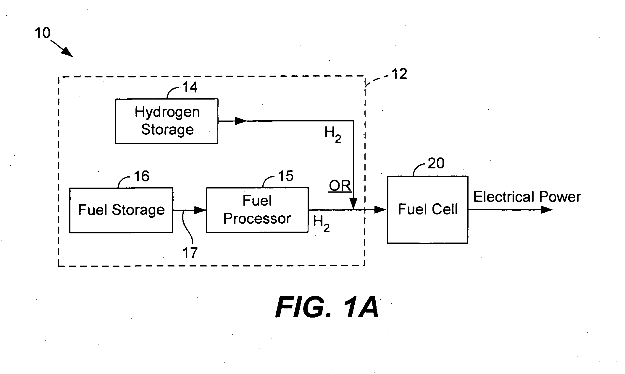
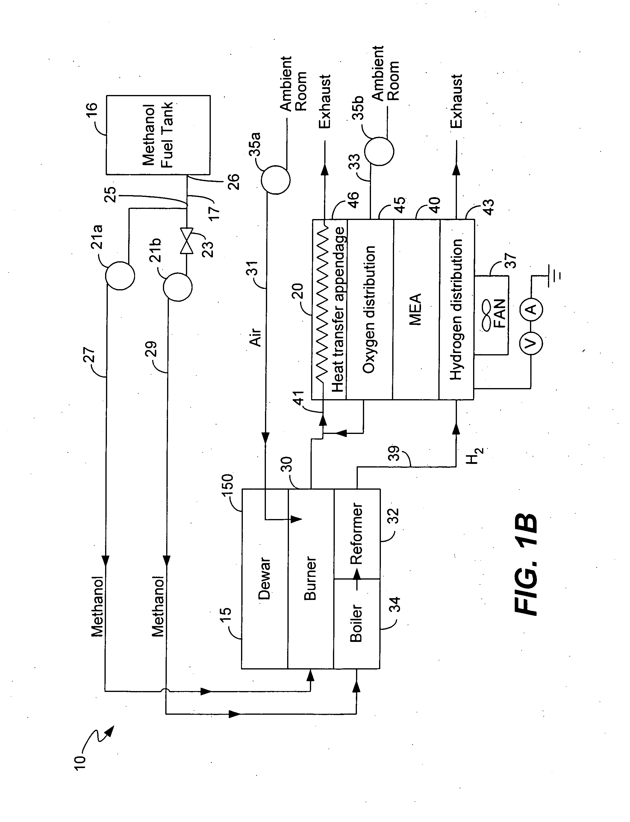
[0053]FIG. 1A illustrates a fuel cell system 10 for producing electrical energy in accordance with one embodiment of the present invention. Fuel cell system 10 comprises a hydrogen fuel supply 12 and a fuel cell 20.

[0054] Hydrogen supply 12 provides hydrogen to fuel cell 20. As shown, supply 12 includes a hydrogen storage device 14 and / or a ‘reformed’ hydrogen supply. Fuel cel...


PUM

PropertyMeasurementUnit
depthaaaaaaaaaa
depthaaaaaaaaaa
thicknessaaaaaaaaaa

Abstract

The present invention relates to fuel cells and components used within a fuel cell. Heat transfer appendages are described that improve fuel cell thermal management. Each heat transfer appendage is arranged on an external portion of a bi-polar plate and permits conductive heat transfer between inner portions of the bi-polar plate and outer portions of the bi-polar plate proximate to the appendage. The heat transfer appendage may be used for heating or cooling inner portions of a fuel cell stack. Improved thermal management provided by cooling the heat transfer appendages also permits new channel field designs that distribute the reactant gases to a membrane electrode assembly. Flow buffers are described that improve delivery of reactant gases and removal of reaction products. Single plate bi-polar plates may also include staggered channel designs that reduce the thickness of the single plate.

Description

CROSS-REFERENCE TO RELATED APPLICATIONS [0001] This application claims priority under 35 U.S.C. §119(e) from co-pending U.S. Provisional Patent Application No. 60 / 482,981 entitled “Micro machined fuel stack with integral cooling and humidification”, which is incorporated by reference for all purposes; and also claims priority under 35 U.S.C. §119(e) from co-pending U.S. Provisional Patent Application No. 60 / 482,996 entitled “Fuel cell system startup procedure and self-heating apparatus”, which is incorporated by reference for all purposes.BACKGROUND OF THE INVENTION [0002] The present invention relates to fuel cell technology. In particular, the invention relates to fuel cells designed for portable applications. [0003] A fuel cell electrochemically combines hydrogen and oxygen to produce electricity. Fuel cell evolution so far has concentrated on large-scale applications such as industrial size generators for electrical power back-up. [0004] Consumer electronics devices and other po...

Claims


Application Information

Patent Timeline
Patent Type & Authority Applications(United States)
IPC IPC(8): B32B3/28H01MH01M2/00H01M2/02H01M2/08H01M2/14H01M8/02H01M8/04H01M8/10
CPCH01M8/0202Y02E60/525H01M8/0215H01M8/0221H01M8/0228H01M8/0234H01M8/0247H01M8/0258H01M8/026H01M8/0267H01M8/0297H01M8/04007H01M8/04059H01M8/04067H01M8/04089H01M8/0618H01M8/1011H01M8/2465H01M2008/1095H01M2008/1293H01M2300/0008Y02E60/50Y02E60/523H01M8/0206H01M8/2483H01M8/242H01M8/0273
Inventor KAYE, IAN W.
Owner ULTRACELL LLC
Learn More