Location estimation of wireless terminals through pattern matching of deduced and empirical signal-strength measurements

Active Publication Date: 2005-01-20
POLARIS WIRELESS
View PDF16 Cites 25 Cited by
  • Summary
  • Abstract
  • Description
  • Claims
  • Application Information

AI Technical Summary

Benefits of technology

Furthermore, the accuracy of the estimate of the location of a wireless terminal can be enhanced when the signal strength of each signal at each location is quantified. A simplified example illustrates this point. If a particular radio station is known to be received in one location with a stre

Problems solved by technology
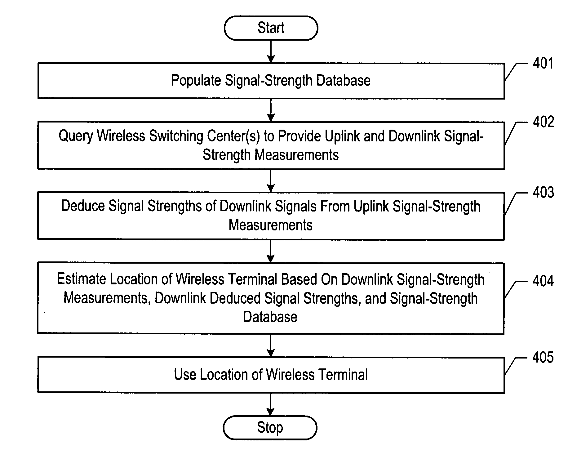
On the other hand, the salient disadvantage of wireless telecommunications lies in that fact that because the user is mobile, an interested party might not be able to readily ascertain the location of the user.
The first technique is only accurate, however, to a few kilometers, and, therefore, it is generally not acceptable for applications (e.g., emergency ser

Method used


Image

  • Location estimation of wireless terminals through pattern matching of deduced and empirical signal-strength measurements
  • Location estimation of wireless terminals through pattern matching of deduced and empirical signal-strength measurements
  • Location estimation of wireless terminals through pattern matching of deduced and empirical signal-strength measurements

Examples


Example

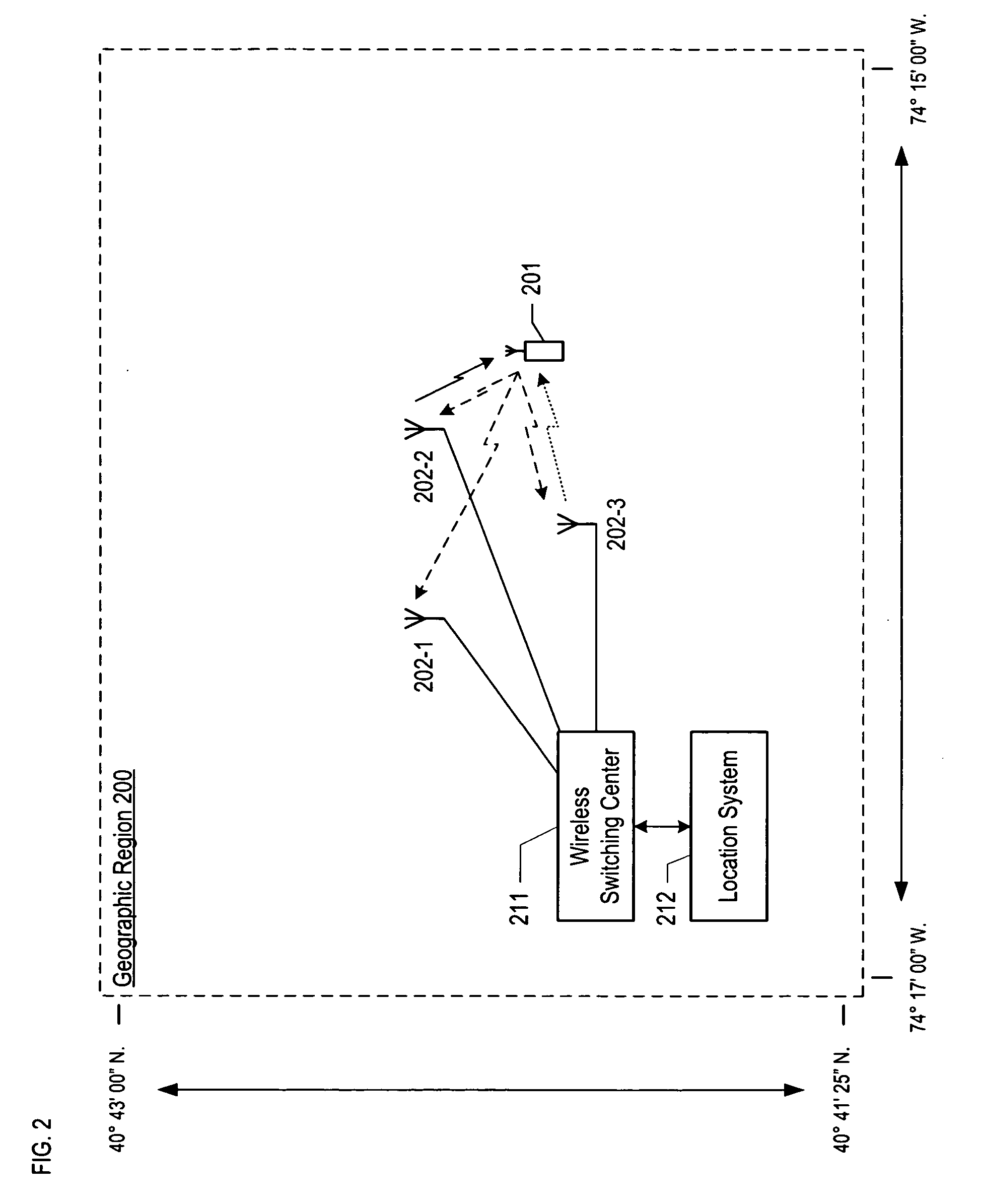
FIG. 2 depicts a map of the illustrative embodiment of the present invention, which comprises: wireless switching center 211, location system 212, base stations 202-1, 202-2, and 202-3, and wireless terminal 201, which are interconnected as shown. The illustrative embodiment provides wireless telecommunications service to most of geographic region 200, in well-known fashion, and is also capable of estimating the location of wireless terminal 201 within geographic region 200.

The illustrative embodiment operates in accordance with the Global System for Mobile Communications (formerly known as the Groupe Speciale Mobile), which is ubiquitously known as “GSM.” After reading this disclosure, however, it will be clear to those skilled in the art how to make and use embodiments of the present invention that operate in accordance with other protocols, such as the Universal Mobile Telephone System (“UMTS”), CDMA-2000, and IS-136 TDMA.

Wireless switching center 211 is a switching center as...


PUM


Abstract

A method of estimating the location of a wireless terminal is disclosed. The illustrative embodiment of the present invention is based on the observation that the signal strength of a signal from a transmitter is different at some locations, and, therefore, the location of a wireless terminal can be estimated by comparing the signal strength it currently observes against a map or database that correlates locations to signal strengths. Furthermore, the illustrative embodiment deduces the signal strength of one or more base stations' control channels at the wireless terminal based on the principal of reciprocity, whether or not the wireless terminal can actually receive the base stations' control channels but so long as the base station can receive and measure the uplink signal from the wireless terminal. The deduced signal-strength measurements can then used—alone or in combination with the empirical signal-strength measurements—to estimate the location of the wireless terminal.

Description

FIELD OF THE INVENTION The present invention relates to telecommunications in general, and, more particularly, to a technique for estimating the location of a wireless terminal. BACKGROUND FIG. 1 depicts a map of a geographic region that is serviced by a wireless telecommunications system, which system provides wireless telecommunications service to wireless terminals (e.g., wireless terminal 101) within the region. The heart of the telecommunications system is wireless switching center 110, which might also be known as a mobile switching center (“MSC”) or a mobile telephone switching office (“MTSO”). Typically, wireless switching center 111 is connected through a plurality of intermediate network elements (e.g., base station controllers, etc.) to a plurality of base stations (e.g., base stations 102-1, 102-2, and 102-3), which are dispersed throughout the geographic area serviced by the system. As depicted in FIG. 1, base station 102-2 serves wireless terminal 101. As is well kn...

Claims


Application Information

Patent Timeline
IPC IPC(8): G01S5/02G01S19/03H04W64/00
CPCH04W64/00G01S5/0252G01S5/02521
Inventor SPAIN, DAVID STEVENSON JR.MARTIN, ROBERT LEWISBHATTACHARYA, TARUN KUMAR
Owner POLARIS WIRELESS
Why Eureka
Try Eureka