Battery life monitor and battery state of charge monitor

a battery life monitor and battery state technology, applied in the field of battery life monitors and battery state of charge monitors, can solve the problems of affecting the usefulness of the battery to store electrical energy, and affecting the accuracy of the reading of the charge sta

Inactive Publication Date: 2005-01-27
YUASA BATTERY UK
View PDF8 Cites 133 Cited by
  • Summary
  • Abstract
  • Description
  • Claims
  • Application Information

AI Technical Summary

Benefits of technology

In this way a relatively accurate reading of the state of charge can be achieved. Preferably the predetermined level is a threshold level below which the battery can be considered to effectively be in equilibrium.

Problems solved by technology

However the instantaneous state of charge of the battery does not give a good indication of the future life of the battery, or how many times it can be recharged before it will fail.
These irreversible changes progressively degrade the ability of the battery usefully to store electrical energy.
These methods require specialist test equipment, cannot be applied frequently and need detailed technical knowledge for the interpretation of the results.
Furthermore, it is intrinsic to sealed batteries that electrolyte is not accessible in the battery cells, and that the battery voltage is dependent on the conditions under which the battery is being used.
Thus, when the state of charge is calculated from the terminal voltage, it is difficult to get a reliable reading of the terminal voltage from which to calculate the state of charge.
Another difficulty with the above approach is that the deliverable electrical capacity and the impedance of an electric storage battery do not change significantly during the majority of the life of the battery.
Measurement of these characteristics as isolated events can only provide information about the current capability of the battery and does not allow predictive evaluation.
Towards the end of the battery's life, the capacity and impedance values of an electric storage battery change more rapidly and comparisons with earlier tests have been used to indicate that failure is imminent.
When such measurements are made repeatedly, through the life of the battery, it is often difficult to assure that the tests are performed reproducibly and that records are maintained reliably enough for accurate technical evaluation to be performed.
However because the indicator is based on a comparison of instantaneous readings with the initial calibration, the battery's history is not properly taken into account.
Therefore for some purposes the monitor may not give as accurate or timely prediction of the battery's future performance as desired.
As noted above, in most cases the maximum state of charge and internal resistance of the battery only change significantly near the end of a battery's life, which limits the information given by this method.
However, there is no analysis of these figures.

Method used


Image

  • Battery life monitor and battery state of charge monitor
  • Battery life monitor and battery state of charge monitor
  • Battery life monitor and battery state of charge monitor

Examples


Embodiment Construction

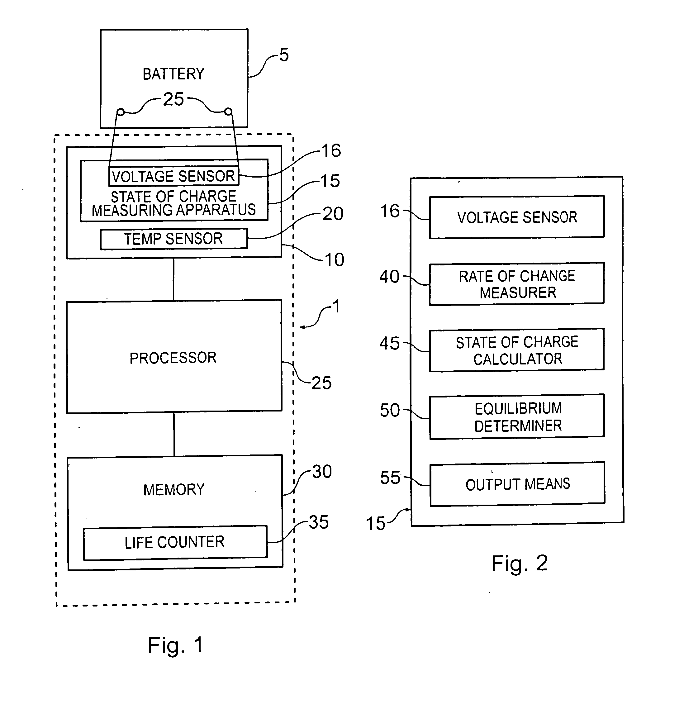
A battery monitor 1 shown schematically in FIG. 1 is integrated into the casing of a Lead acid battery 5. The battery monitor 1 comprises a monitor 10 for taking measurements from the battery. The monitoring means comprises a state of charge measuring means 15 including a voltage sensor 16 which is permanently connected to the terminals 25 of the battery and configured to measure the voltage across the terminals 25. The monitor 10 also includes a temperature sensor 20 for measuring the temperature of the battery 5. Because the battery monitor 1 is integrated into the battery casing the temperature sensor 20 effectively reads the battery temperature. In alternative embodiments in which the battery monitor is not integral with the battery the temperature sensor may be mounted on the battery and transmit data to the monitor 10.

The battery monitor 1 also comprises a processor in the form of processor 25 and a memory 30 for storing a life counter 35 having a life counter value represent...


PUM


Abstract

The electrolyte inside a lead and acid battery is inaccessible and measurements of the voltage across a battery's terminals do not necessarily give a good indication of the future performance of a battery. Furthermore, although the state of charge of a battery can be determined from measurement of the voltage across its terminals, these measurements will be misleading unless they are taken when the battery is in equilibrium. Accordingly, the present invention proposes a battery monitor which takes measurements from a battery and is configured to detect one or more types of event affecting the battery life and to subtract a predetermined amount from a life counter representing the remaining available life of the battery, each time such an event is detected. The monitor is also configured to calculate the state of charge of the battery, but only when the battery is in equilibrium.

Description

BACKGROUND OF THE INVENTION 1. Field of the Invention This invention relates to the monitoring and prediction of the remaining useful life of an electric storage battery, such as a Lead acid battery. It also relates to determination of the state of charge of the battery. It is thought that the present invention will assist current supply management for systems using batteries as alternative or primary sources of electric power. 2. Summary of the Prior Art The state of charge of a battery is a measure of the instantaneous energy level of the battery and is expressed as a percentage from 0%, when the battery is flat, to 100% for a fully charged battery, which has not yet been used. For a Lead acid battery the state of charge can be determined from the open circuit terminal voltage of the battery, as there is an approximately linear relationship between the two. However the instantaneous state of charge of the battery does not give a good indication of the future life of the batte...

Claims


Application Information

Patent Timeline
Patent Type & Authority Applications(United States)
IPC IPC(8): G01R31/36
CPCG01R31/3606G01R31/3679G01R31/3668G01R31/3655H01M10/48G01R31/382G01R31/392G01R31/379Y02E60/10
Inventor REES, GLYNNESTEVENSON, PETER
Owner YUASA BATTERY UK
Why Eureka
Try Eureka