Battery heating circuit

Active Publication Date: 2005-01-27
MATHEWS ASSOCS
View PDF42 Cites 32 Cited by
  • Summary
  • Abstract
  • Description
  • Claims
  • Application Information

AI Technical Summary

Benefits of technology

[0015] The present invention overcomes the problem when a cell or battery has a minimum operating voltage (the “cut-off voltage”) and overcomes the problem resulting at lower temperatures where the powered equipment reaches its cut-off voltage prematurely while the cell or battery has remaining stored capacity. The present invention provides a simple circuit design using a temperature sensor and heating built into the battery. The temperature sensor detects when the cell or battery temperat

Problems solved by technology

Many batteries must be disposed of in a reliable manner because of the inherent risk of fire or explosion created by the improper use or disposal of batteries.
If a cell is hazardous, such as lithium, and contacts the water, it could explode.
This method is generally crude and unreliable.
Other battery discharge systems offer some improvement, but still pose problems.
Similar to other prior art battery discharge mechanisms and systems, these disclosed systems could be unreliable because they often use electromechanical and/or other types of moving or unreliable parts.
This requirement becomes critical when the battery contains a lithium cell that could explode upon contact with water.
These seals, however, have often proven unreliable, particularly when the internal pressure in the battery increases because of temperature changes or altitude changes.
One drawback that may not be adequately addressed by prior art proposals is that associated with the increase in internal battery resistance, which increases significantly at these lower temperatures.
In most battery applications, the

Method used


Image

  • Battery heating circuit
  • Battery heating circuit
  • Battery heating circuit

Examples


Embodiment Construction

[0028] The present invention will now be described more fully hereinafter with reference to the accompanying drawings, in which preferred embodiments of the invention are shown. This invention may, however, be embodied in many different forms and should not be construed as limited to the embodiments set forth herein. Rather, these embodiments are provided so that this disclosure will be thorough and complete, and will fully convey the scope of the invention to those skilled in the art. Like numbers refer to like elements throughout.

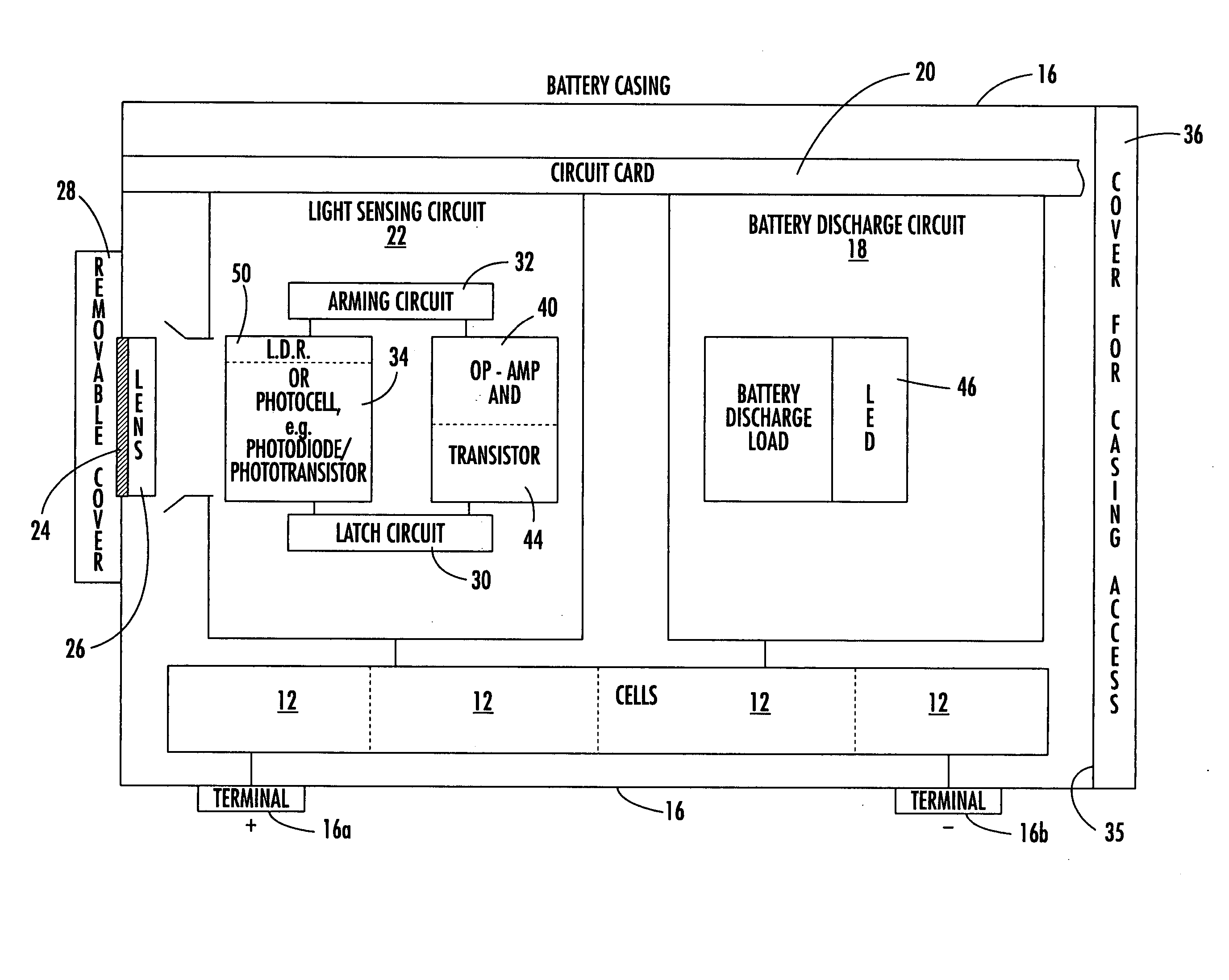
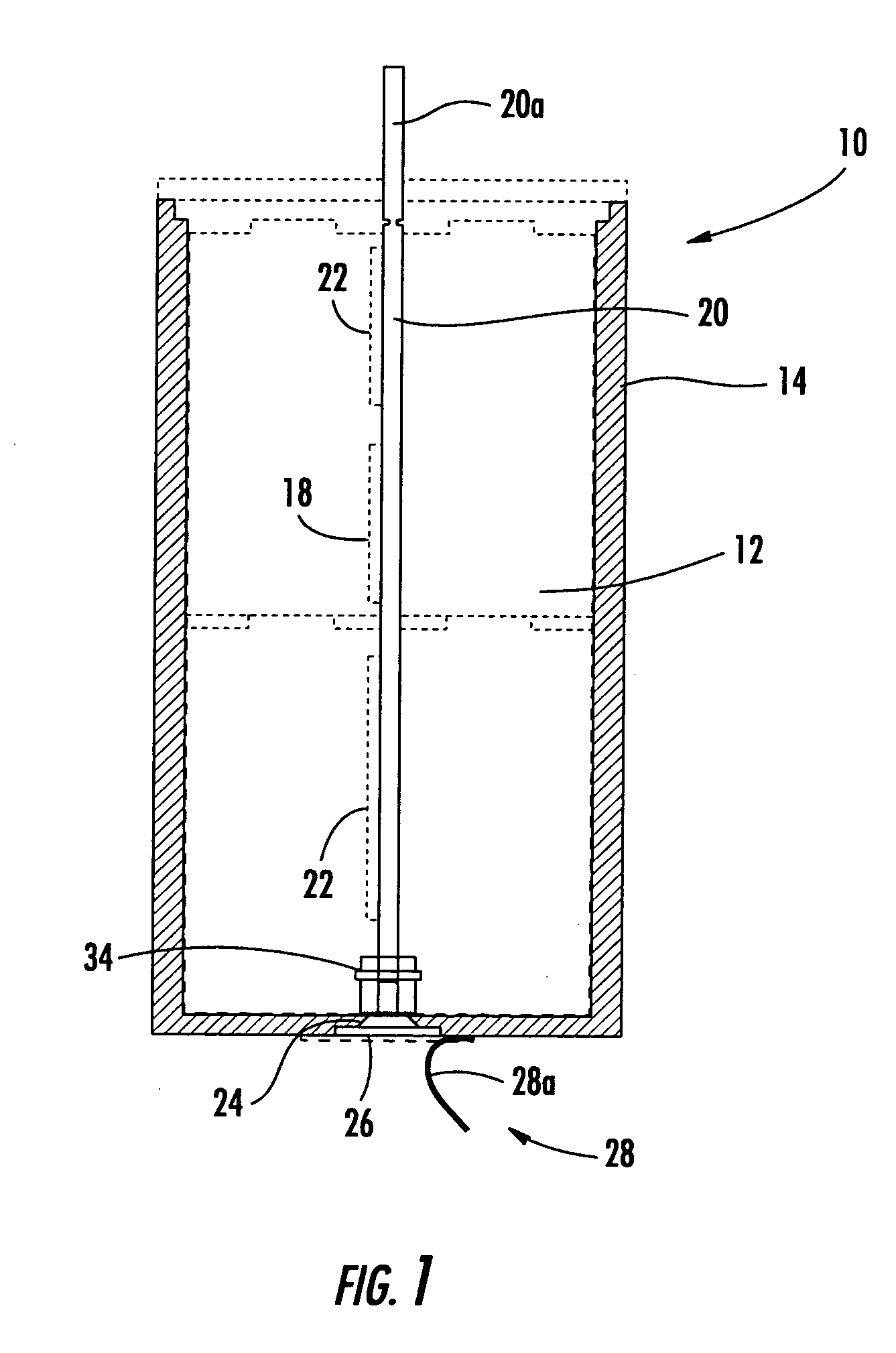
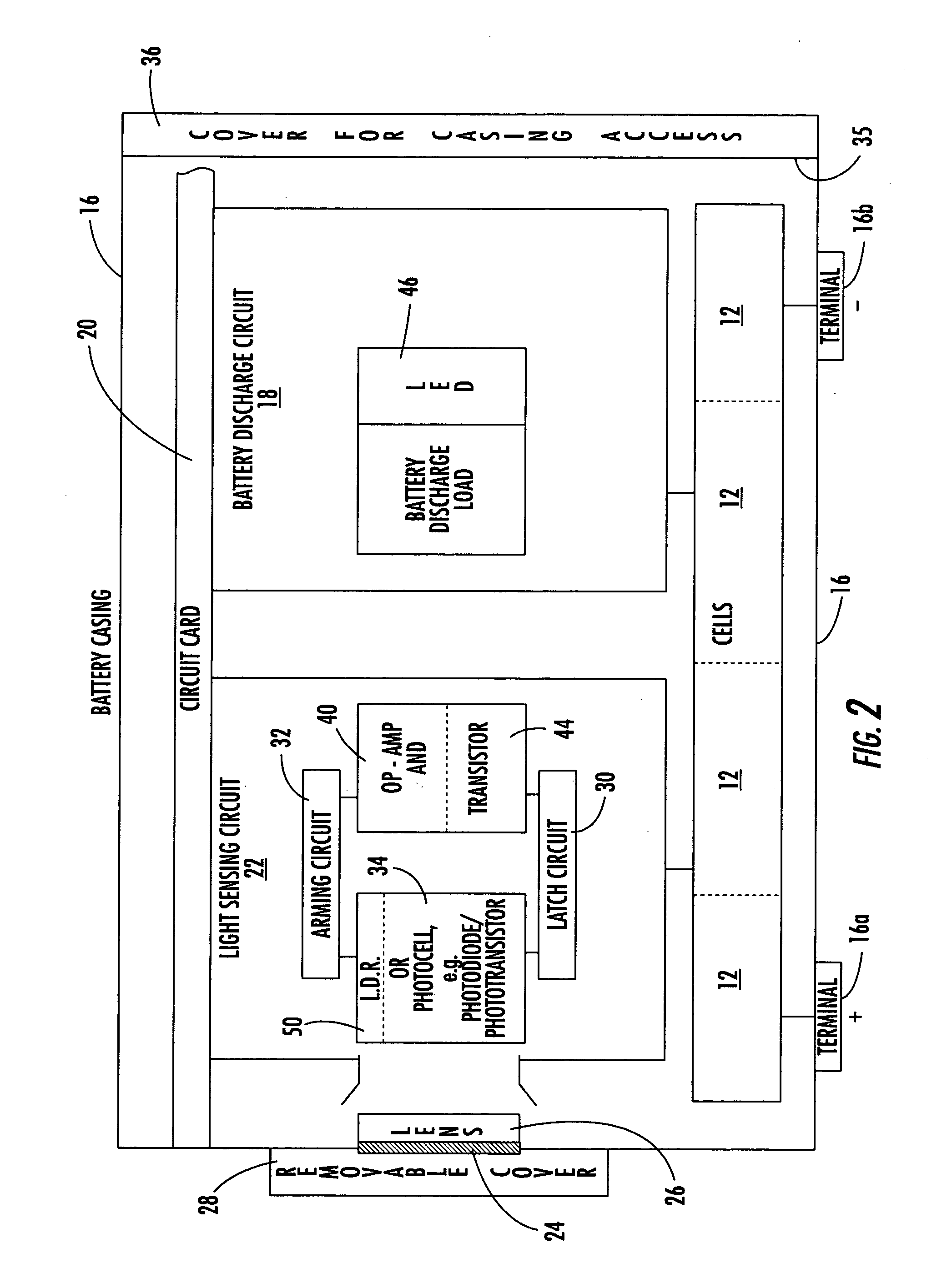
[0029] For purposes of description and background, the battery discharge circuit disclosed in the '738 application will be set forth relative to FIGS. 1-3. After describing in detail a battery discharge circuit relative to FIGS. 1-3, a description of other circuits that could operate alone or in conjunction with the battery discharge circuit will be set forth in detail. An example of a battery heater circuit of the present invention is shown in FIG. 4. T...


PUM


Abstract

A battery delivers its rated capacity when the battery is below a temperature when the available battery capacity is limited. The battery includes a heating element, a temperature sensor, and a switch operatively connected to the heating element and temperature sensor and responsive to the temperature sensor for switching on the heating element and raising the temperature of the battery to allow the battery to deliver its rated capacity when a sensed temperature of the battery is below a temperature where available battery capacity is limited.

Description

RELATED APPLICATION [0001] This is a continuation-in-part patent application based upon prior filed copending utility application Ser. No. 10 / 452,738, filed Jun. 2, 2003, which is based on prior filed provisional application Ser. No. 60 / 396,292 filed Jul. 17, 2002, the disclosures which are hereby incorporated by reference in their entirety.FIELD OF THE INVENTION [0002] This invention relates to batteries, and more particularly, to batteries with heating and discharge circuits. BACKGROUND OF THE INVENTION [0003] The copending patent application Ser. No. 10 / 452,738 (“the '738 application”) addresses the problem where federal, state and local agencies require many types of batteries, including primary or rechargeable batteries, for example lithium batteries as one example only, to be discharged completely prior to discarding the battery. Many batteries must be disposed of in a reliable manner because of the inherent risk of fire or explosion created by the improper use or disposal of ...

Claims


Application Information

Patent Timeline
IPC IPC(8): H01M50/569H02J7/00
CPCH01M2/348H01M10/486H02J7/0063H01M10/5026H01M10/5004H01M10/637H01M10/613Y02E60/10H01M50/581H02J7/007194H02J7/00712H01M50/569
Inventor KAMENOFF, ROBERT
Owner MATHEWS ASSOCS
Why Eureka
Try Eureka