High side power switch with charge pump and bootstrap capacitor

a high-side power switch and capacitor technology, applied in the field of power switches, can solve the problem that the maximum frequency of operation of intelligent power switches is limited to about 1 khz, and achieve the effect of high-speed switching operations

Active Publication Date: 2005-01-27
INFINEON TECH AMERICAS CORP
View PDF6 Cites 7 Cited by
  • Summary
  • Abstract
  • Description
  • Claims
  • Application Information

AI Technical Summary

Benefits of technology

[0005] It is an object of the present invention to provide a power switching device which is capable of continuous on operation, when desired, and

Problems solved by technology

Further, in a pulsed mode of operation, the maximum frequency of operation of intelligent power switches has been limited to about 1 khz for sili

Method used


Image

  • High side power switch with charge pump and bootstrap capacitor
  • High side power switch with charge pump and bootstrap capacitor

Examples


Embodiment Construction

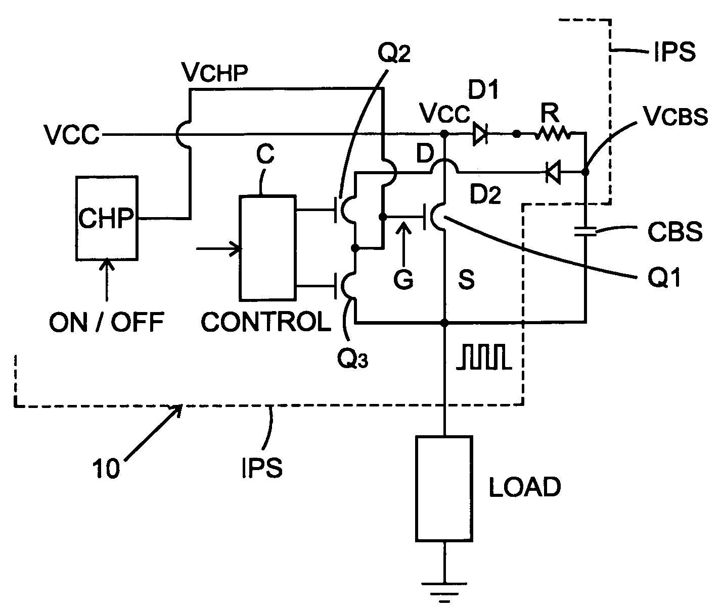
[0012] With reference now to the drawings, FIG. 1 shows a circuit according to the present invention. All components, with the exception of the load and the capacitor CBS, can be integrated into an integrated circuit denominated IPS in FIG. 1. IPS is an abbreviation for “intelligent power switch”.

[0013] The circuit according to the present invention comprises a power switch 10 including a main power switching device Q1, typically driven by a driver circuit employing two transistors Q2 and Q3 in a half bridge arrangement. The gate of transistor Q1 is driven by the common node between transistors Q2 and Q3.

[0014] The drain of transistor Q1 is connected, in typical fashion to the voltage source VCC. The anode of a diode D1 is connected to the voltage source VCC in series with a resistor R. The other end of the resistor R is coupled to a bootstrap capacitor CBS. A second diode D2 has its anode coupled to the common junction of resistor R and capacitor CBS. The cathode of diode D2 is c...


PUM


Abstract

A power switching circuit comprising a power semiconductor switching device, a charge pump circuit having a control input to control whether it is on or off and a charge pump output, the charge pump output being coupled to a control terminal of the power semiconductor switching device, a bootstrap power supply for supplying power to driver circuitry for the power semiconductor switching device, the bootstrap power supply comprising a bootstrap capacitor coupled to a charging current source, the bootstrap power supply providing power to the driver circuitry when the power semiconductor switching device is being switched by the driver circuitry in a pulsed mode, and the charge pump supplying a control voltage to turn on the power semiconductor switching device and maintain it on when the power switching semiconductor device is to be maintained on continuously.

Description

BACKGROUND OF THE INVENTION [0001] The present invention relates to power switches, and in particular to semi-conductor power switches, particularly power MOSFET switches. The present invention has particular application to intelligent power switches which are power switching devices that include intelligent protective circuits to prevent damage in the event of overtemperature and overcurrent conditions. [0002] Intelligent power switches employ charge pumps which are well known circuits to charge current into the gate of the power switching device in order to maintain the power switch on continuously. In particular, charge pumps are necessary for high side NMOS switches when a voltage above the supply voltage needs to be generated. Further, in a pulsed mode of operation, the maximum frequency of operation of intelligent power switches has been limited to about 1 khz for silicon integrated charge pumps because pump capacitor values are small and cannot generate large gate currents ev...

Claims


Application Information

Patent Timeline
IPC IPC(8): H01LH03B1/00H03K3/00H03K17/06H03K19/00
CPCH03K17/063
Inventor DE FRUTOS, XAVIERNADD, BRUNO C.THIERY, VINCENTLEE, CHIK YAM
Owner INFINEON TECH AMERICAS CORP
Why Eureka
Try Eureka