Projector

a projector and projector technology, applied in the field of projectors, can solve the problems of high manufacturing cost of such apparatuses, and achieve the effects of reducing the amount of red light incident on the light modulating unit, increasing the amount of red light, and reducing the luminan

Active Publication Date: 2005-01-27
SEIKO EPSON CORP
View PDF2 Cites 47 Cited by
  • Summary
  • Abstract
  • Description
  • Claims
  • Application Information

AI Technical Summary

Benefits of technology

[0010] In this projector, the numbers of LEDs in the respective light emitting units are set so that when all of the LEDs are lit (i.e., emit light), red light, green light, and blue light are emitted from the respective light emitting units with a ratio of 24:70:6, for example. Accordingly, unlike the conventional construction where luminance is reduced by supplying currents of different value to the respective light emitting units, the light emitting performance of all of the LEDs can be sufficiently utilized and the respective light emitting units can be composed of the minimum required number of LEDs, so that a considerable reduction can be made in the manufacturing cost of the projector.
[0011] In this case, the light source should preferably include tone adjusting LEDs that are controlled and lit separately from the LEDs disposed so as to satisfy the predetermined condition and are used to increase an amount of at least one out of the red light, the green light, and the blue light. With this construction, when changing the image to be projected and displayed on a screen to warm tones, the tone adjusting LEDs (red LEDs) for increasing the amount of red light are...

Problems solved by technology

As a result, since conventional image projecting apparatuses are equipped with equal numbers of high luminance LEDs and low luminance LEDs reg...

Method used


Image

  • Projector
  • Projector
  • Projector

Examples


Embodiment Construction

[0019] A preferred embodiment of a projector according to the present invention will now be described with reference to the attached drawings.

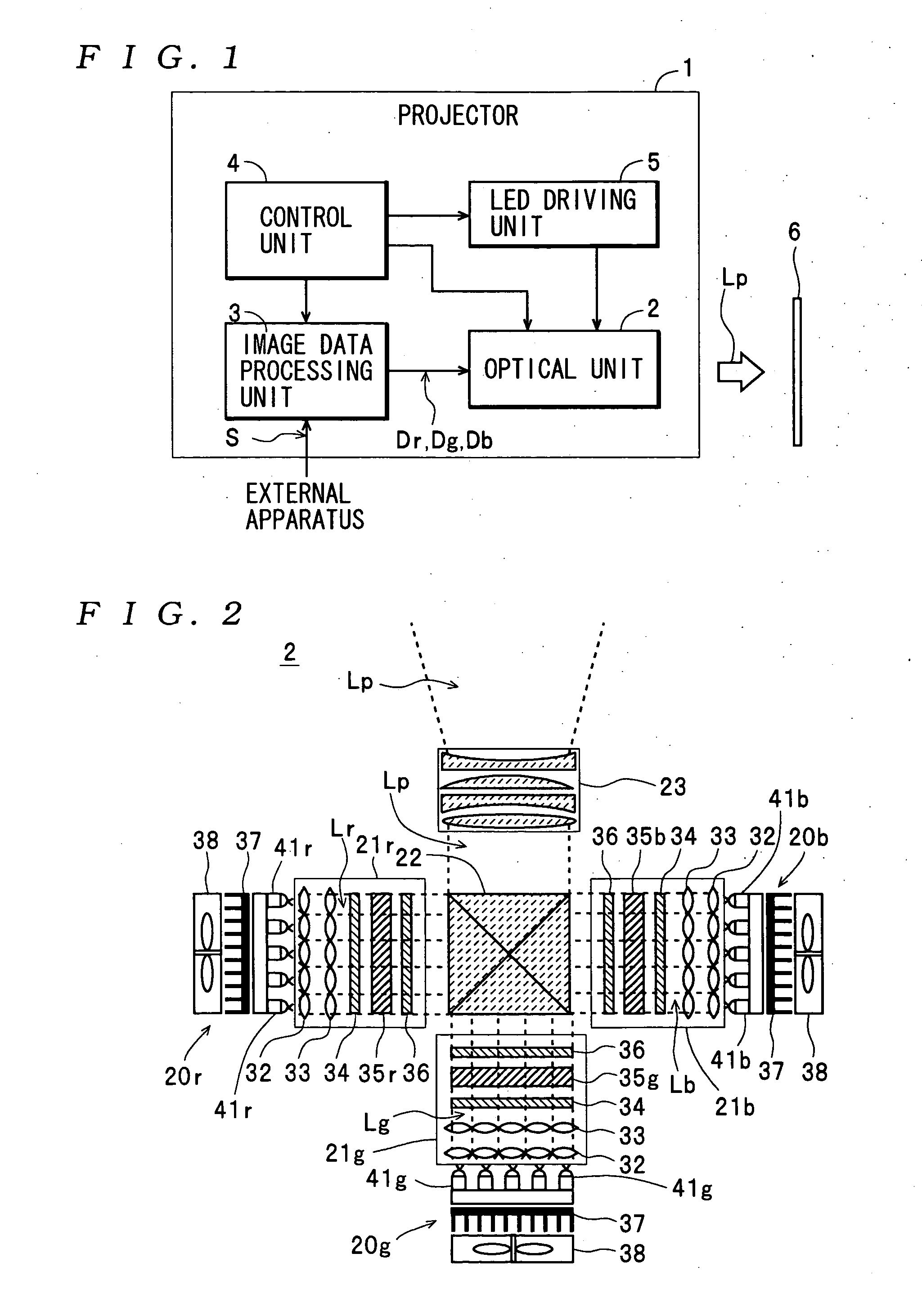
[0020] The construction of a projector 1 will be described first. The projector 1 shown in FIG. 1 is a three-panel projector that is equipped with three liquid crystal light valves 35, described later, and which separately modulates red light, green light, and blue light before combining the modulated light. The projector 1 is constructed so as to be able to project and display various types of color images on a screen 6 based on an image signal S outputted by an external apparatus (a reproduction apparatus such as a video deck or a DVD player or a personal computer). More specifically, the projector 1 includes an optical unit 2, an image data processing unit 3, a control unit 4, and a LED driving unit 5. It should be noted that in reality, the projector 1 actually also includes an audio signal processing unit, a speaker, and the like, but fo...


PUM


Abstract

A project is provided that includes a light source including three light emitting units in which a plurality of LEDs are disposed and which emits red light, green light, and blue light. A liquid crystal light valve is provided that modulates the red light, the green light, and the blue light emitted from the light source. The projector is constructed so as to be capable of projecting and displaying an image on a screen by projecting the light modulated by the liquid crystal light valve onto the screen. The light source is constructed with one out of the light emitting units including a different number of LEDs than the other light emitting units so that a ratio between respective amounts of red light, green light, and blue light incident on the liquid crystal light valve with all of the LEDs lit satisfies a predetermined condition.

Description

RELATED APPLICATIONS [0001] This application claims priority to Japanese Patent Application No. 2003-166835 filed Jun. 11, 2003 which is hereby expressly incorporated by reference herein in its entirety. BACKGROUND OF THE INVENTION [0002] 1. Field of the Invention [0003] The present invention relates to a projector constructed so as to be able to modulate light emitted from a light source including light emitting diodes and to project and display an image on a screen. [0004] 2. Description of the Related Art [0005] To reduce power consumption and apparatus size, a projector that uses high-intensity light emitting diodes (LEDs) as a light source in place of a light source such as a high-pressure mercury lamp has been proposed. As one example of this type of projector, Japanese Laid-Open Patent Publication No. 2002-244211 discloses an image projecting apparatus equipped with LED light sources including a plurality of LEDs. In this case, one LED light source is formed of a plurality of...

Claims


Application Information

Patent Timeline
IPC IPC(8): G03B21/00G03B21/14G03B21/10H04N9/31
CPCH04N9/315Y10S362/80H04N9/3197G03B21/10G03B21/00
Inventor HOSAKA, TOSHIYUKI
Owner SEIKO EPSON CORP
Why Eureka
Try Eureka