
Laser power meter

a laser power meter and laser power technology, applied in the direction of heat measurement, optical radiation measurement, instruments, etc., can solve problems such as source or error, and achieve the effects of accurate laser power measurement, increased accuracy of power meter, and low cos

Active Publication Date: 2005-01-27
COHERENT INC
View PDF8 Cites 13 Cited by
  • Summary
  • Abstract
  • Description
  • Claims
  • Application Information

AI Technical Summary

Benefits of technology

Another aspect of the present invention is a low cost, laser power meter. Different configurations of this laser power meter can be used to measure laser power preferably within (but not limited to) the range of 10 W to 10 kW. Each configuration can accurately measure laser power over a dynamic range of at least ten times (i.e., a 100 W detector will measure between 10 W-100 W). Unlike other power meters, multiple measurement of laser power can be made with the present invention without first cooling the absorber to room temperature. This feature is due to a mathematical algorithm that corrects for heat loss due to convection. Multiple measurements can be taken until the absorber reaches its maximum operating temperature, which is preferably about 150° C. A calibration algorithm is used that computes the variation in convection with laser power and temperature. This calibration routine dramatically increases the accuracy of the power meter when taking multiple measurements. Without the calibration algorithm, measurement error would increase dramatically with absorber temperature. Also, the present invention computes and averages instantaneous power, rather than measuring the total temperature change in an absorber over a timed interval like other power meters.

Problems solved by technology

A disadvantage of this type of power meter is that it ignores convection losses from the absorber.
Starting a measurement with the absorber at an elevated temperature would introduce a source or error due to the temperature dependence of convection losses.

Method used


Image

  • Laser power meter
  • Laser power meter
  • Laser power meter

Examples


Embodiment Construction

The drawings depict various preferred embodiments of the present invention for purposes of illustration only. One skilled in the art will readily recognize from the following discussion that alternative embodiments of the structures and methods illustrated herein may be employed without departing from the principles of the invention described herein.

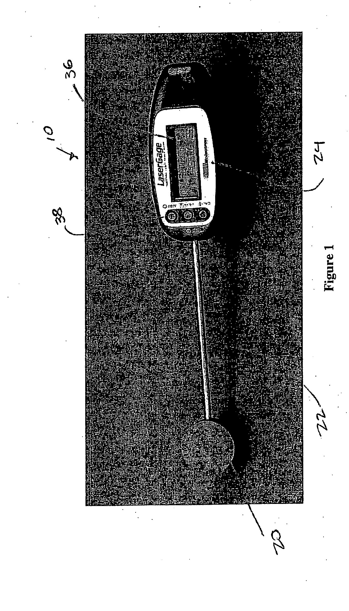
Shown in FIG. 1, the laser power meter 10 of the present invention has three main parts; an absorber 20, a stainless steel stem 22, and a computation and readout unit 24.

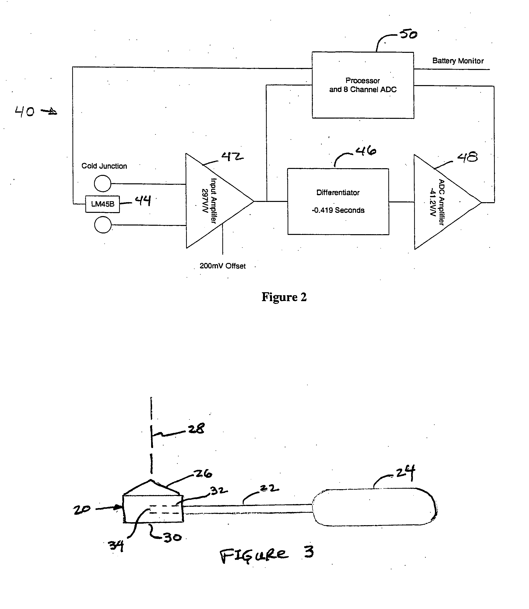
The absorber 20 is a mass of a thermally-conductive material, such as copper or aluminum, that is coated with a material that is resistant to laser damage. As best shown in FIG. 3, the absorber shape is preferably a cone with a rounded apex joined to a short cylinder. The absorber 20 has a conical portion 26 that is oriented toward the laser beam 28, plus a cylindrical portion 30 opposite the laser beam. The laser beam impinges on the rounded apex of the cone. The t...


PUM

PropertyMeasurementUnit
poweraaaaaaaaaa
temperatureaaaaaaaaaa

Abstract

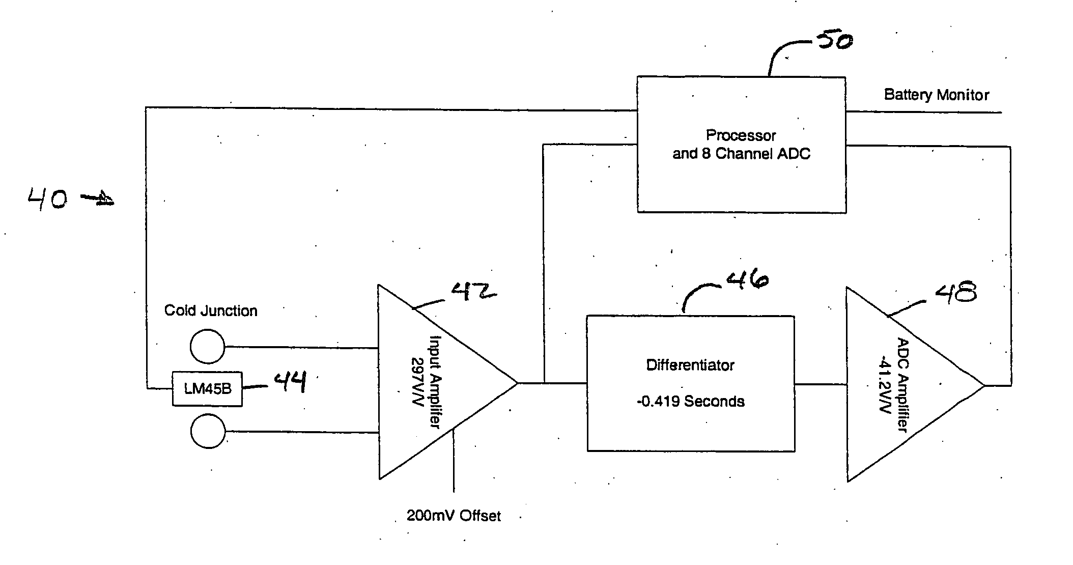
A laser power meter and associated method are disclosed. The laser power meter has an absorber that is placed in a path of a laser beam during a power measurement, a temperature sensor for measuring the temperature of the absorber, a differentiator for determining a rate of change of the temperature of the absorber, and a processor that computes an estimated power of the laser beam based on the temperature and its rate of change without considering power related loss effects and then computes the power of the laser beam based on the estimated power and the temperature and its rate of change.

Description

BACKGROUND OF THE INVENTION 1. Field of the Invention This invention relates generally to methods and apparatus for measuring the power of a laser, and relates more particularly to a laser power meter having an absorber mass and a circuit that monitors the temperature of the absorber mass and compensates for convection losses during a power test. 2. Description of the Relevant Art One way to measure power or energy in a laser beam is to expose a mass to the laser beam and measure the amount of heat absorbed by the mass over a period of time. The mass absorbs incident laser radiation and converts the optical energy of the laser beam into heat. This heat ultimately flows to a heat sink that is held at a near constant ambient temperature by either air or water cooling. The temperature difference between the absorber mass and heat sink is converted into an electrical signal by a temperature sensor, such as a thermocouple or thermistor. In order to obtain a measurable temperature dif...

Claims


Application Information

Patent Timeline
Patent Type & Authority Applications(United States)
IPC IPC(8): G01J1/02G01J1/42G01K17/00
CPCG01J1/02G01K17/003G01J1/4257G01J1/0233
Inventor SCHLOSS, JAMESLEVINGSTON, SIDNEY E.BERGMAN, SEAN
Owner COHERENT INC
Learn More