Optical system for reinforcing optical tweezers capturing force

a technology of optical system and force, which is applied in the direction of nuclear engineering, manufacturing tools, instruments, etc., can solve the problems of increased spherical aberration, difficult control and use of optical tweezers to trap micro particles, and failure to catch micro particles

Inactive Publication Date: 2005-01-27
JAPAN SCI & TECH CORP
View PDF1 Cites 3 Cited by
  • Summary
  • Abstract
  • Description
  • Claims
  • Application Information

AI Technical Summary

Benefits of technology

[0021] The trapping force reinforcing optical system for optical tweezers, wherein, in the optics of the optical tweezers, an additional lens system movable along the optical axis may be positioned on the optical axis between the laser light source and collector lens, and the spherical aberration of the collector lens may be controlled by moving the additional lens system along the optical axis and at the same time a spot mirror may be positioned behind the collector lens to cut off the laser beam at the center part and enhance the trapping force through synergistic effects;
[0026] The present invention may furthermore provide a trapping force reinforcing optical system for optical tweezers, wherein, in the optics of the optical tweezers provided with a beam expander, an additional lens system movable along the optical axis may be positioned on the optical axis between the lenses comprising the beam expander, and the spherical aberration of the beam expander may be controlled by moving the additional lens system along the optical axis, and at the same time a spot mirror may be positioned behind the beam expander to cut off the laser beam at the center part of the laser bean and enhance the trapping force through synergistic effects; and

Problems solved by technology

In actual applications, however, it is often difficult to control and use the optical tweezers to trap micro particles.
Problems are experienced using the conventional optics shown in FIG. 5; beads of under several micrometers in size may not be trapped by the objective, and even when trapping is successful the trapping force sharply decreases when the particles are at a depth of 5 μm or more in the water, eventually resulting in trapping failures.
The major cause of the problem is the increased spherical aberration that increases with the depth of the beads in the water due to refraction occurring at the interface between the water and glass (also called cover glass).
When studying biological specimens under a microscope, however, the specimen is often damaged if near-infrared rays on the specimen exceed a few mW.
This procedure is therefore not very practical.

Method used


Image

  • Optical system for reinforcing optical tweezers capturing force
  • Optical system for reinforcing optical tweezers capturing force
  • Optical system for reinforcing optical tweezers capturing force

Examples


Embodiment Construction

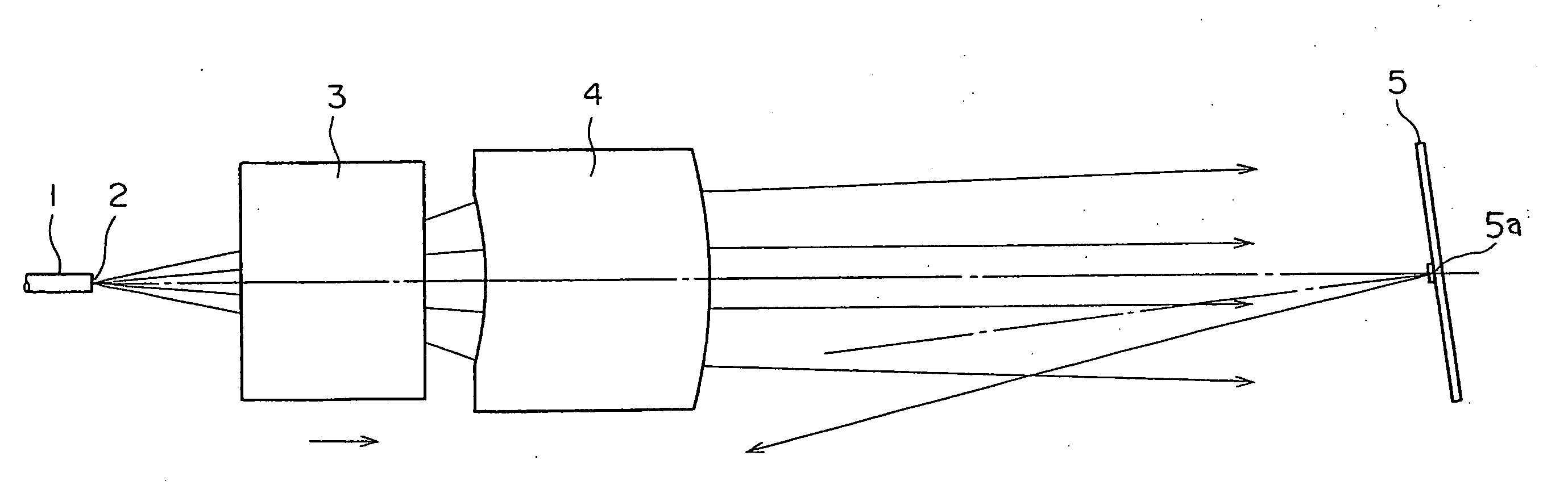
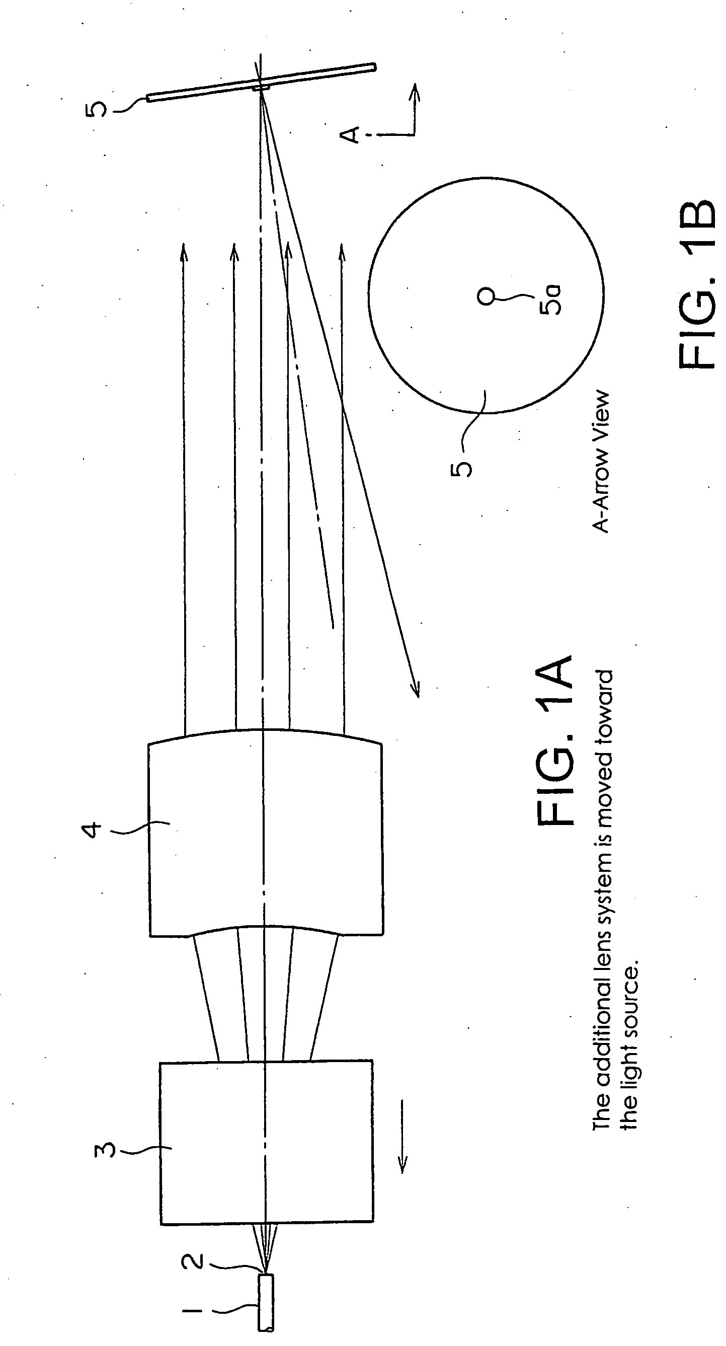
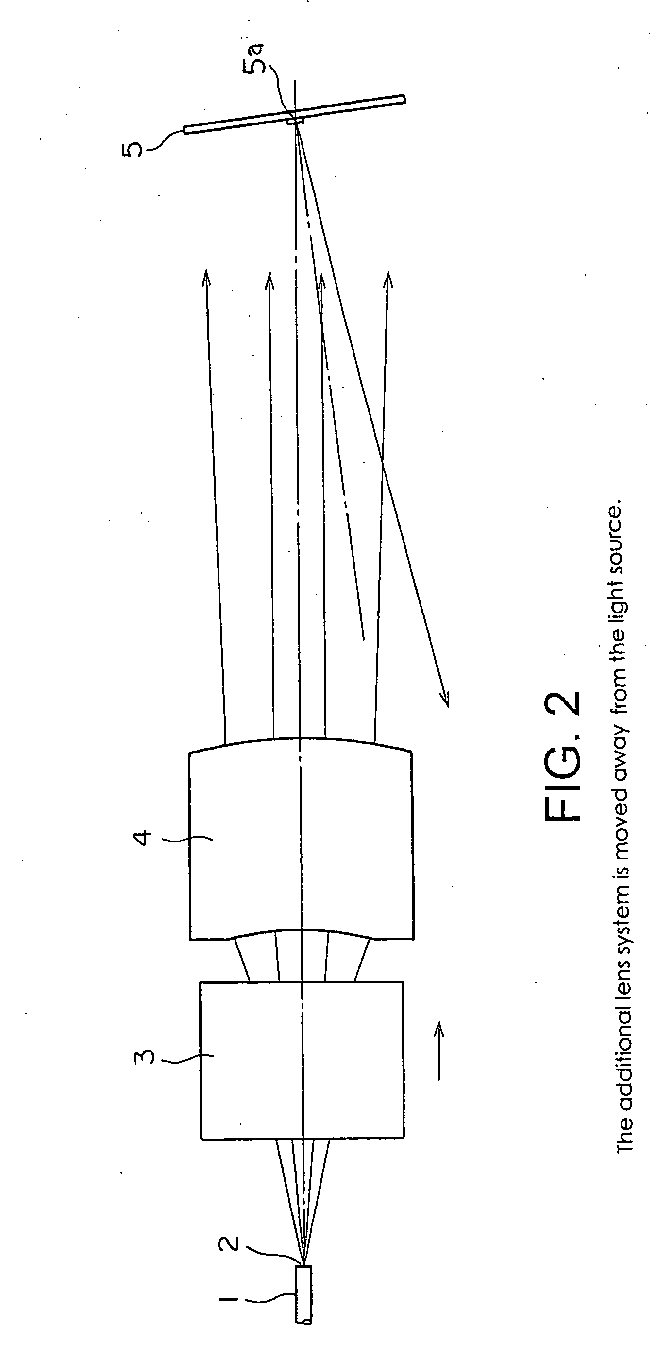
[0033] The principle of the optics of the present invention is described in the following referring to the drawings. FIGS. 1A and 1B shows the optics of the present invention where the additional lens system is moved toward the light source. FIG. 2 shows the optics of the present invention where the additional lens system is moved away from the light source.

[0034] In FIGS. 1A, 1B and 2, 1 denotes the laser fiber light source, 2 the emission port, 3 the additional lens system, 4 the collector lens and 5 the spot mirror. These components are arranged as shown in the figures. The additional lens system (3) moves along the optical axis, between the emission port (2) and the collector lens (4), as driven by a suitable known means of travel (not shown). The additional lens system is mounted on and removed from the optical axis using a suitable means of attachment.

[0035] The compound focal distance of the additional lens system (3) is infinity (no power lens). The additional lens system ...


PUM


Abstract

The trapping force reinforcing optical system that enables optical tweezers to trap micro particles under water securely, without contact and non-invasively using a laser beam. The optics of the optical tweezers comprises an additional lens system movable along an optical axis, and a spherical aberration of a collector lens is controlled by moving the additional lens system along the optical axis.

Description

TECHNICAL FIELD [0001] The present invention relates to a trapping force reinforcing optical system that enable optical tweezers to trap micro particles under water securely, without contact and non-invasively using a laser beam. BACKGROUND ART [0002] Optical tweezers are a means of trapping micro particles underwater without contact and non-invasively using laser beams that are converged by an objective of a large numerical aperture. The principle was first announced by Ashkin in 1986 and was then followed by research on practical applications. At present, a variety of related devices and systems are available in the market. [0003] Optical tweezers are a valuable tool in biological and physical research. In actual applications, however, it is often difficult to control and use the optical tweezers to trap micro particles. [0004] Conventional optical tweezers are briefly described below. FIG. 5 shows the optics of optical tweezers. [0005] In FIG. 5, 101 denotes the laser fiber light...

Claims


Application Information

Patent Timeline
Patent Type & Authority Applications(United States)
IPC IPC(8): B25J7/00B81B7/00G02B21/32G21K1/00H01S3/00H01S3/101
CPCG02B21/32
Inventor KINOSHITA, KAZUHIKOSHIO, MEGUMI
Owner JAPAN SCI & TECH CORP
Why Eureka
Try Eureka