Localized pole tip heating device for magnetic head for hard disk drive

a technology of heating device and hard disk drive, which is applied in the field of localized heating device of the pole tip of the magnetic head, can solve the problems achieve the effects of reducing data writing rate, reducing pole tip stress, and reducing magnetization switching speed

Active Publication Date: 2005-01-27
WESTERN DIGITAL TECH INC
View PDF4 Cites 26 Cited by
  • Summary
  • Abstract
  • Description
  • Claims
  • Application Information

AI Technical Summary

Benefits of technology

[0006] The magnetic head of the present invention is formed with a narrow pole tip, such that the track width that is written on the magnetic media of the hard disk drive is correspondingly narrow. However, such narrow pole tips have decreased magnetization switching speeds that result in decreased data writing rates. In the present invention a pole tip heating element is fabricated to reduce the pole tip stress and increase its permeability, such that the magnetization switching speed is increased. The heating element is preferably electrically interconnected within the induction coil circuit of the magnetic head, such that the electrical current flowing through the induction coil also flows through the heating element. In the preferred embodiment, the heating element is electrically connected in series with the induction coil. In this electrically connected configuration there is no increase in the number of electrical leads to the magnetic head, as the heating element receives its electrical current through the existing two electrical connections for the induction coil. In a preferred embodiment, the heating element is fabricated above the second magnetic pole, such that the fabrication steps for forming the heating element do not interfere with the preexisting process steps for fabricating the major components of the head. The heating element may have a resistance of from 0.2 to 1.0 ohms, and is preferably formed with a resistance of approximately 0.3 to 0.6 ohms, such that the approximately 40 mA current that flows through the induction coil and the heating element creates a heating energy of the heating element of approximately 0.5 mW. The heating element can be comprised of a variety of materials such as Cu, W, NiFe, NiCr and IrRh.

Problems solved by technology

However, such narrow pole tips have decreased magnetization switching speeds that result in decreased data writing rates.

Method used


Image

  • Localized pole tip heating device for magnetic head for hard disk drive
  • Localized pole tip heating device for magnetic head for hard disk drive
  • Localized pole tip heating device for magnetic head for hard disk drive

Examples


first embodiment

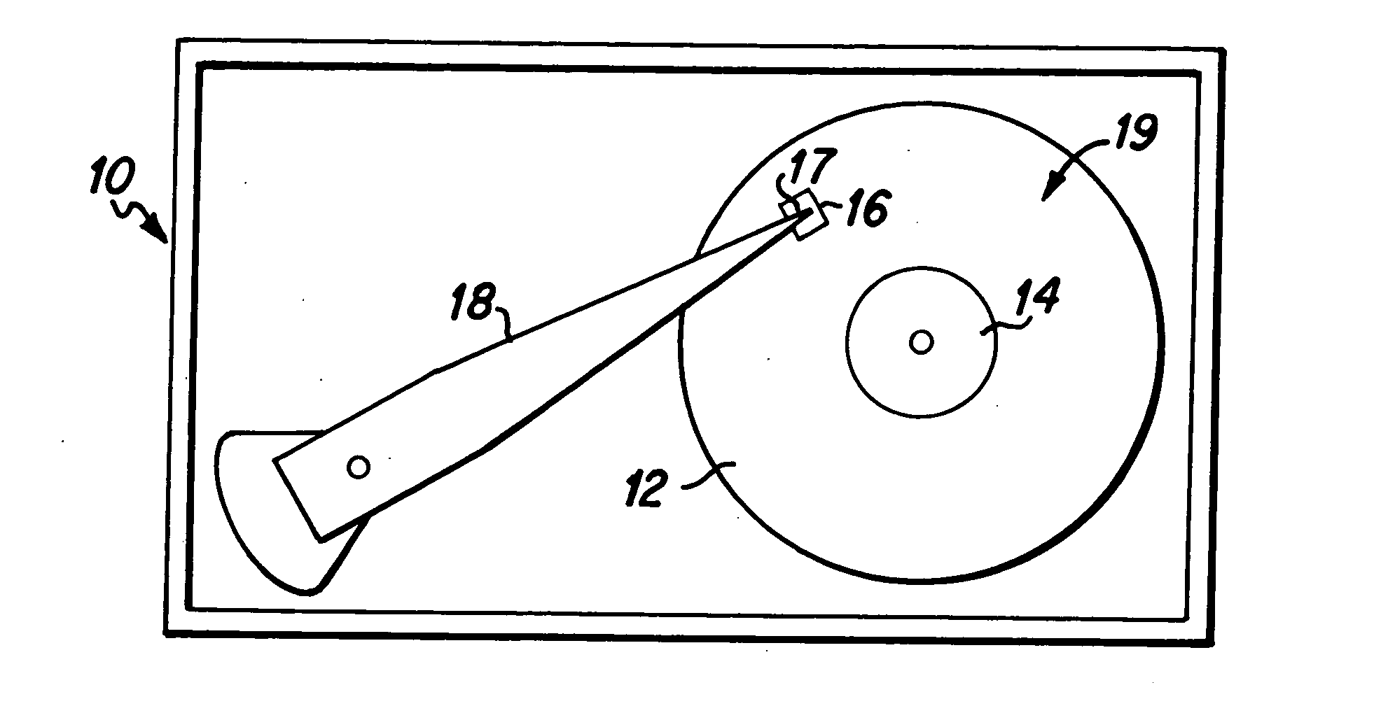
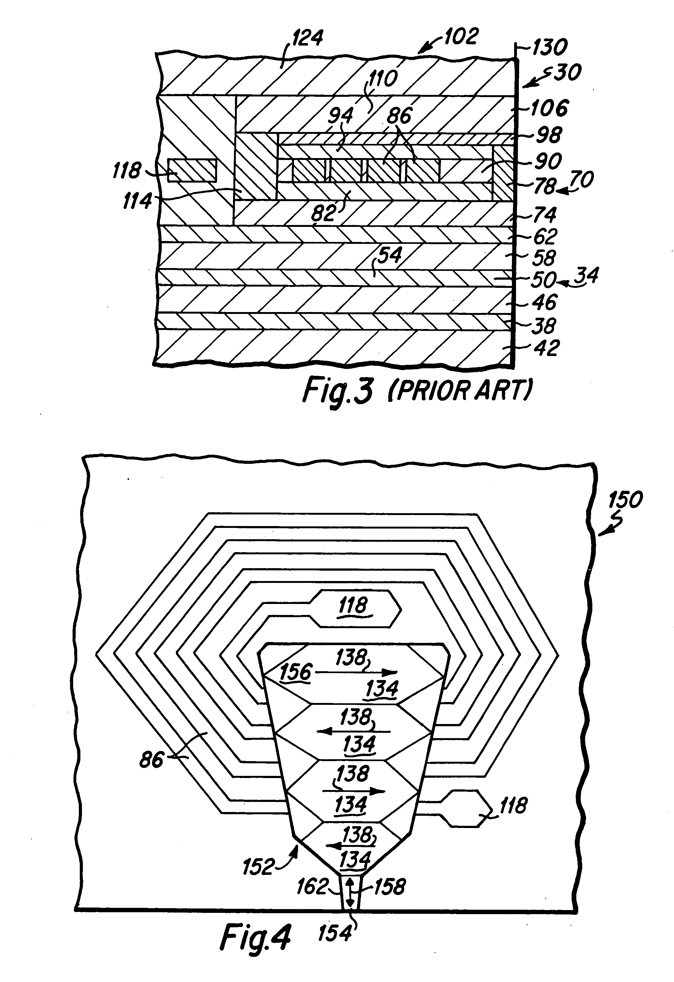
[0036] the present invention is depicted in FIGS. 5 and 6, wherein FIG. 5 is a top plan view depicting components of the write head portion of a magnetic head 170 of the present invention that is suitable for use as the magnetic head 16 in the disk drive 10 depicted in FIG. 1, and FIG. 6 is a side cross-sectional view taken along lines 6-6 of FIG. 5. Initially, in comparing the head 170 depicted in FIG. 5 with that depicted in FIG. 4, it is to be noted that the second magnetic pole yoke 156 and pole tip 154 of the head 150 depicted in FIG. 4 is substantially identical to that utilized within the magnetic head 170 depicted in FIG. 5. Basically, the magnetic head 170 of the present invention, as depicted in FIGS. 5 and 6, includes a pole tip heating element 180 that is fabricated proximate the pole tip 154 to provide heat energy to the pole tip 154. It has been found that where the pole tip 154 is sufficiently heated, the permeability of the pole tip material is increased, pole tip st...

embodiment 220

[0039] A first alternative embodiment 220 of the present invention is depicted in FIG. 7, which is a top plan view that is similar to FIG. 5. The heater element 224 depicted in FIG. 7 is an augmentation of the heater element 180 depicted in FIG. 5, wherein an additional thickness of electrically conductive material 228 is deposited upon the electrical leads 190 and 198 of the heater element 180 depicted in FIG. 5. The additional electrically conductive metal portions 228 serve to reduce the electrical resistance of the electrical leads of the heater element 224, such that the significant electrical resistance of the heater element 224 is even more localized at the narrow heating portions 194 above the pole tip. This results in a more efficient heating of the pole tip of the magnetic head 220.

embodiment 250

[0040] Another alternative embodiment 250 of the present invention is depicted in FIGS. 8 and 9, wherein FIG. 8 is a top plan view of the write head portion of the magnetic head 250, and FIG. 9 is a side cross-sectional view taken along lines 9-9 of FIG. 8. As depicted in FIGS. 8 and 9, and with reference to the embodiment of the present invention depicted in FIGS. 5 and 6, the significant difference between the embodiments 250 and 170 is the addition of a second electrically conductive leg 254 to the heating element 258 depicted in FIGS. 8 and 9. Basically, the additional leg 254 provides a second electrically conductive path. By controlling the width of the second leg 254, relative to the width of the heating element 194, the quantity of electrical current flowing through the heating element 194 is controlled, whereby the quantity of heat provided by the heating element 194 is likewise controlled. As can be seen in FIG. 9, both legs 180 and 254 of the heating element 258 are fabri...


PUM

PropertyMeasurementUnit
electrical resistanceaaaaaaaaaa
widthaaaaaaaaaa
resistanceaaaaaaaaaa

Abstract

The magnetic head is formed with a narrow pole tip, and a pole tip heating element is fabricated to reduce the pole tip stress and increase its permeability, such that the magnetization switching speed of the pole tip is increased. The heating element is preferably electrically interconnected within the induction coil circuit of the magnetic head, such that the electrical current flowing through the induction coil also flows through the heating element. In a preferred embodiment, the heating element is fabricated above the second magnetic pole. The heating element is preferably formed with a resistance of approximately 0.2 to 1.0 ohms, such that the approximately 40 mA current that flows through the induction coil and the heating element creates a heating energy of the heating element of approximately 0.3 to 1.6 mW. The heating element can be comprised of a variety of materials such as Cu, W, NiFe, NiCr and IrRh.

Description

BACKGROUND OF THE INVENTION [0001] 1. Field of the Invention [0002] The present invention relates generally to magnetic heads for hard disk drives, and more particularly to a heating device for the localized heating of the pole tip of the magnetic head. [0003] 2. Description of the Prior Art [0004] The continual quest to increase the areal data storage density of magnetic media has resulted in the reduction in the width of the writing head magnetic pole tip of the magnetic head, such that a narrower track width is created and more tracks per inch (TPI) can be recorded in the media. Simultaneously, there is the quest to increase the data rate at which data bits are written to the magnetic media. State of the art pole tips are currently created having a pole tip width of approximately 0.25 microns in response to the desire to increase TPI, and data rates are approaching 1 Gb / second. A problem that arises when such narrow pole tips are driven at such high data rates is that rapid magne...

Claims


Application Information

Patent Timeline
Patent Type & Authority Applications(United States)
IPC IPC(8): G11B5/00G11B5/012G11B5/10G11B5/17G11B5/31G11B5/39
CPCG11B5/012G11B5/17G11B5/3103G11B5/3113G11B5/3116G11B2005/0013G11B5/3143G11B5/3967G11B2005/0002G11B2005/0005G11B2005/0008G11B5/3133
Inventor HSIAO, WEN-CHIEN DAVIDLAM, QUAN-CHIU HARRY
Owner WESTERN DIGITAL TECH INC
Why Eureka
Try Eureka