Method of operating an array of laser sources integrated in a monolithic chip or in a photonic integrated circuit (PIC)

a laser source and monolithic chip technology, applied in the field of wavelength tuning of laser sources integrated on a chip or in a photonic integrated circuit, can solve the problems of difficult to manufacture arrays of dfb laser sources with wavelength grids, dfb laser arrays with wavelength grids, and dfb laser arrays with awg optical multiplexers. , to achieve the effect of reducing the loss of insertion

Inactive Publication Date: 2005-01-27
INFINERA CORP
View PDF6 Cites 47 Cited by
  • Summary
  • Abstract
  • Description
  • Claims
  • Application Information

AI Technical Summary

Benefits of technology

[0077] According to this invention, a method of operating an array of laser sources integrated as an array in a single monolithic chip comprises the steps include designing the laser sources to have different target emission wavelengths so that together they form a spectral emission wavelength grid, coupling outputs from the laser sources to an array of gain / loss elements also integrated on the single monolithic chip, one each receiving the output from a respective laser source; and adjusting the outputs with the gain / loss elements so that the power levels of the laser source array across are substantially uniform.

Problems solved by technology

The principal reason is that it is difficult to fabricate, on a repeated basis, an array of DFB lasers with a wavelength grid that simultaneously matches the wavelength grid of the a wavelength selective combiner (e.g., an AWG).
However, these types of laser sources are more difficult to manufacture in an array and in monolithic form compared to DFB laser sources.
But again, the integration of a DFB laser array with an AWG optical multiplexer with matching of their respective wavelength grids is difficult to achieve.
Furthermore, none of these reference demonstrates the combination of modulated sources, such as, a modulated laser source (either directly modulated or externally modulated) with any type of source laser (DFB or DBR) in combination with a frequency selective multiplexer or combiner.

Method used


Image

  • Method of operating an array of laser sources integrated in a monolithic chip or in a photonic integrated circuit (PIC)
  • Method of operating an array of laser sources integrated in a monolithic chip or in a photonic integrated circuit (PIC)
  • Method of operating an array of laser sources integrated in a monolithic chip or in a photonic integrated circuit (PIC)

Examples


Embodiment Construction

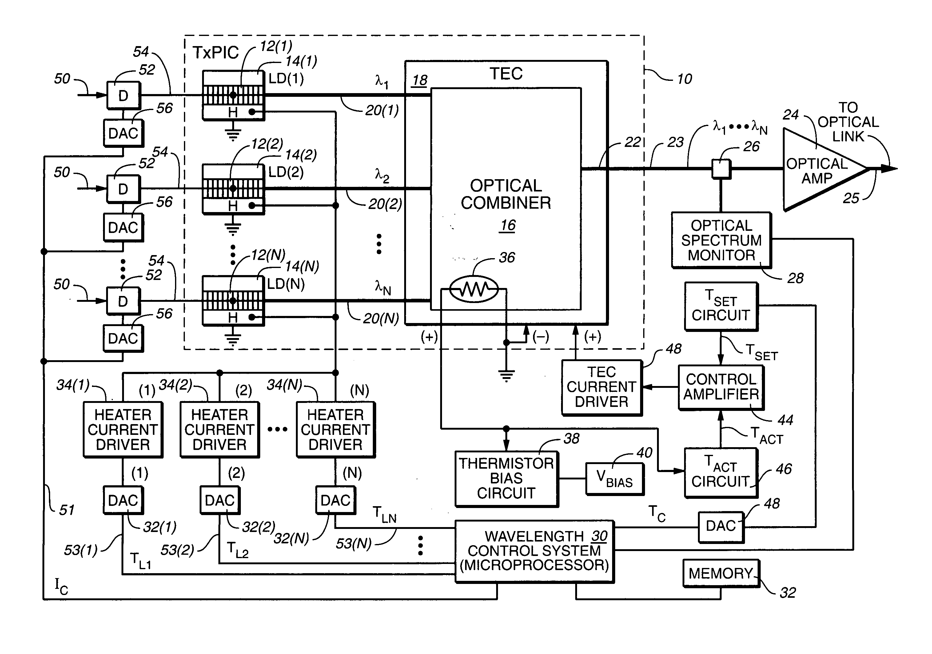
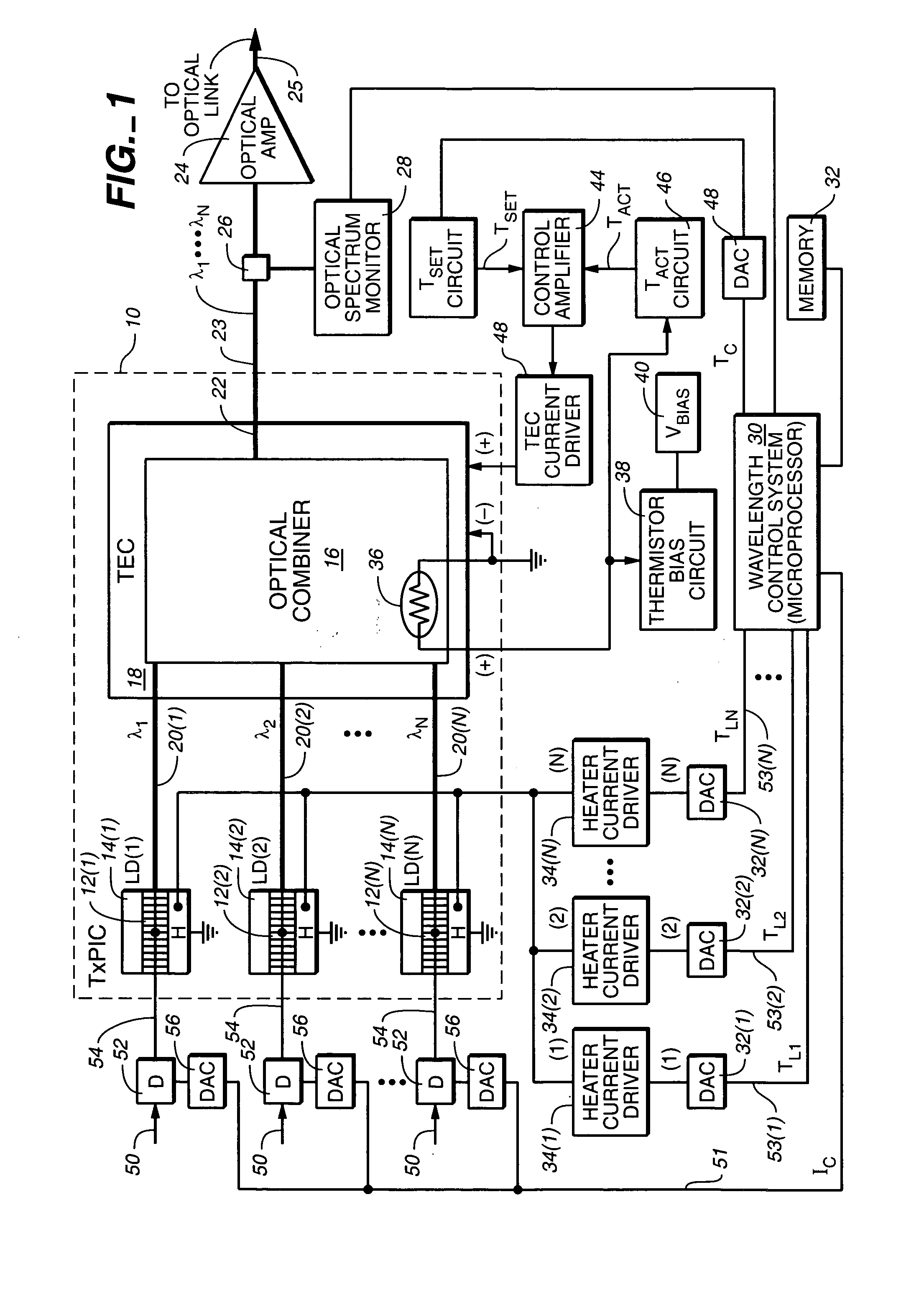
[0114] Reference is now made to FIG. 1 wherein there is shown an example of an embodiment of this invention comprising TxPIC chip 10 utilizing wavelength tuning elements for tuning the modulated source grid with the multiplexer grid, which are shown in FIG. 1 as thermal tuning elements. However, it should be understood that other wavelength tuning elements are contemplated in this invention, such as modulated source tuning by means of changing laser current and bias to change its refractive index and, therefore, the operating wavelength of a laser. Other wavelength tuning elements include: adding multiple sections to the laser and varying the current in each section (including, phase tuning, which is the provision of a phase section in a DFB or DBR laser), vernier tuning where the best passband response is chosen from multiple outputs of the optical multiplexer, the use of coolers to tune the wavelength grid or individual elements of the PIC, including TECs which are also shown in c...


PUM

PropertyMeasurementUnit
temperatureaaaaaaaaaa

Abstract

A method of operating an array of laser sources integrated as an array in a single monolithic chip where the steps include designing the laser sources to have different target emission wavelengths so that together they form a spectral emission wavelength grid, coupling outputs from the laser sources to an array of gain / loss elements also integrated on the single monolithic chip, one each receiving the output from a respective laser source; and adjusting the outputs with the gain / loss elements so that the power levels of the laser source array across are substantially uniform.

Description

REFERENCE TO RELATED APPLICATION [0001] This application is a division of U.S. parent patent application, Ser. No. 10 / 267,330, filed Oct. 8, 2002, which application claims priority to provisional application Ser. No. 60 / 328,207, filed Oct. 9, 2001, now U.S. patent application Ser. No. 10 / 267,331, filed Oct. 8, 2002 and entitled, TRANSMITTER PHOTONIC INTEGRATED CIRCUIT (TxPIC) CHIP ARCHITECTURES AND DRIVE SYSTEMS AND WAVELENGTH STABILIZATION FOR TxPICs; provisional application, Ser. No. 60 / 328,332, filed Oct. 9, 2001, now part of U.S. patent application Ser. No. 10 / 267,331, supra; provisional application, Ser. No. 60 / 370,345, filed Apr. 5, 2002, the provisional application corresponding to U.S. patent application Ser. No. 10 / 267,330; provisional application, Ser. No. 60 / 378,010, filed May 10, 2002, now U.S. patent application Ser. No. 10 / 267,346, filed Oct. 8, 2002 and entitled, TRANSMITTER PHOTONIC INTEGRATED CIRCUIT (TxPIC) CHIP WITH ENHANCED POWER AND YIELD WITHOUT ON-CHIP AMPLIFI...

Claims


Application Information

Patent Timeline
Patent Type & Authority Applications(United States)
IPC IPC(8): G02B6/12G02B6/34G02F1/017H01S3/10H01S3/13H01S5/00H01S5/024H01S5/026H01S5/06H01S5/0625H01S5/0683H01S5/12H01S5/20H01S5/22H01S5/227H01S5/34H01S5/40H01S5/50H04B10/04H04B10/12H04B10/145H04B10/17H04B10/29H04J14/02
CPCB82Y20/00H04J14/02G02B6/12004G02B6/12007G02B6/12019G02B6/12023G02B6/12026G02B6/12028G02B6/12033G02B6/124G02F1/01725G02F2001/0175G02F2001/01758H01S5/0085H01S5/024H01S5/02415H01S5/02453H01S5/02461H01S5/02476H01S5/026H01S5/0261H01S5/0264H01S5/0265H01S5/0268H01S5/0425H01S5/0612H01S5/06256H01S5/06258H01S5/0683H01S5/0687H01S5/12H01S5/1228H01S5/2077H01S5/22H01S5/2214H01S5/2224H01S5/227H01S5/2272H01S5/2275H01S5/3408H01S5/34306H01S5/4025H01S5/4031H01S5/4087H01S5/50H04B10/2914H04B10/50H04B10/506H04B10/572G02B6/02204H01S5/04256G02F1/0175G02F1/01758
Inventor KISH, FRED A. JR.JOYNER, CHARLES H.WELCH, DAVID F.TAYLOR, ROBERT B.NILSSON, ALAN C.
Owner INFINERA CORP
Why Eureka
Try Eureka