
Digital signal processing system and method for a telephony interface apparatus

a digital signal and interface technology, applied in the field of digital signal processing systems and methods for telephony interface apparatuses, can solve the problems of limiting the sound exposure to a fraction of a second, affecting the effectiveness of the device, and affecting the service of subscribers, so as to reduce the level of high-pitched narrow-band signals, the effect of reducing the risk of operators

Inactive Publication Date: 2005-01-27
HEAR WORKS PTY LTD
View PDF3 Cites 100 Cited by
  • Summary
  • Abstract
  • Description
  • Claims
  • Application Information

AI Technical Summary

Benefits of technology

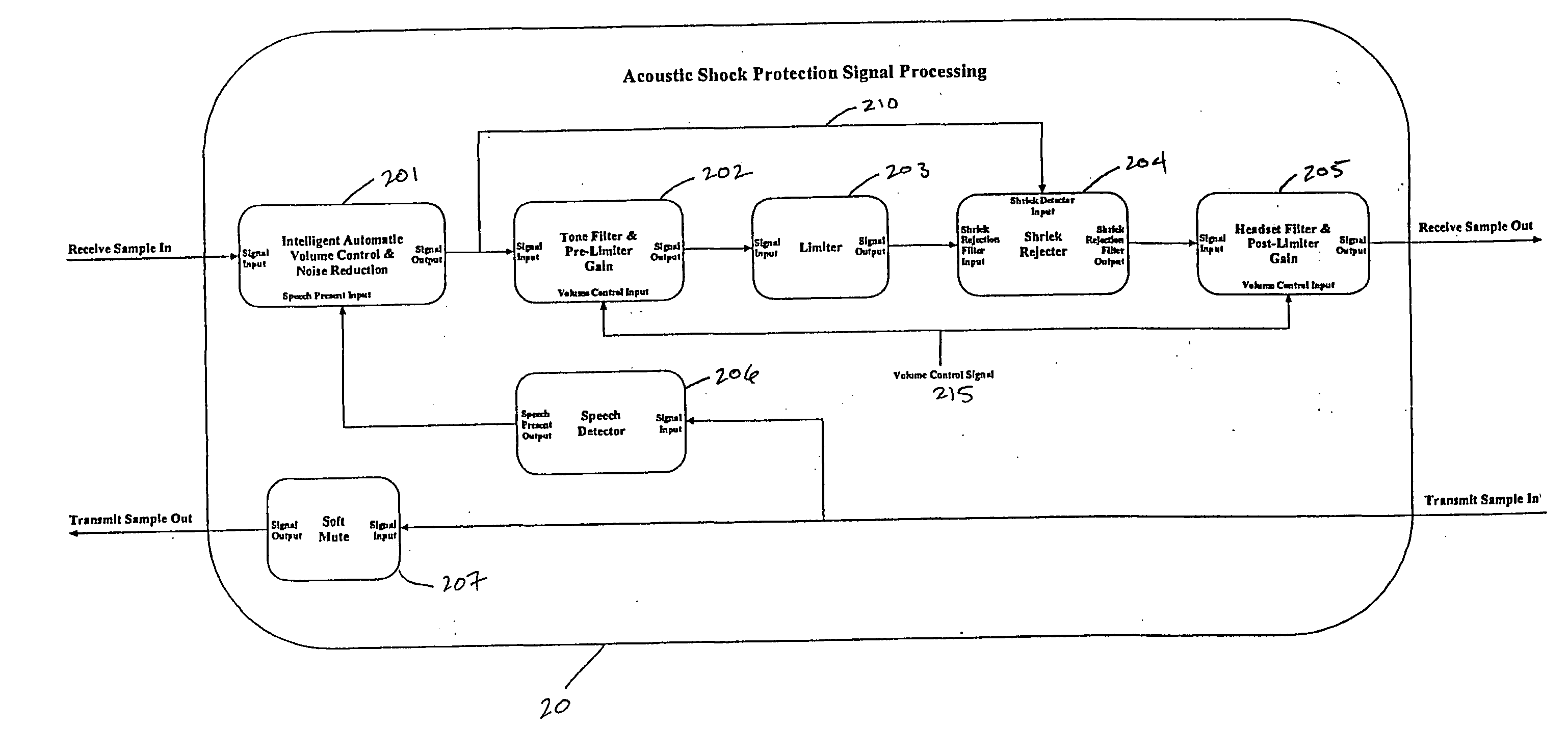
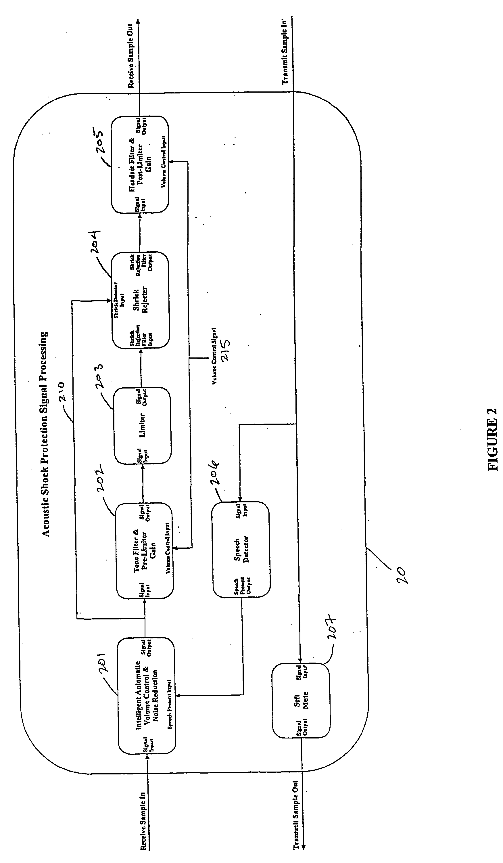
One embodiment of the invention relates to an amplifying device adapted to detect the presence of one or more high-pitched narrow bandwidth signals within audio telephony signals, in isolation or in the presence of speech signals, and perform rapid, selective attenuation of the one or more narrow bandwidth signals to levels lower than those that occur at the same frequencies when speech is received in the absence of such high-pitched signals.

Problems solved by technology

Occasionally, intense, unwanted signals accidentally occur within the telephone network.
Although these narrow-band noises can affect anyone, people using a regular hand-held telephone can quickly move the phone away from their ear, thus limiting their sound exposure to a fraction of a second.
Call-centre operators, however, usually use a headset, which takes considerably longer to remove from the ear were an intense sound to occur.
They thus receive a greater noise exposure than for people using hand-held phones.
The problem may be exacerbated if call centres are so noisy that the operators need to have the volume controls on their telephones turned up higher than would be necessary in a quieter place.
Current methods to protect against acoustic shock involve limiting the voltage delivered to the headsets so that the sound level delivered to the ear is also limited in some way.
The first, peak clipping, acts instantaneously, but simultaneously creates distortion.
Compression limiting creates less distortion, but there is a conflict between the need to reduce the gain slowly (to avoid distortion) and the need to reduce the gain quickly (to provide rapid protection from high level signals on the telephone line).
One problem with current forms of limiting is that the devices limit the voltage delivered to the headset in a frequency-independent manner.
As acoustic shocks are believed to be caused by high-frequency sounds, the standard solution is not well matched to the problem.
An additional (and greater) problem for conventional limiting systems is that there is a severe compromise between selecting a limiting level that is low enough to protect against acoustic shock, but high enough to allow good intelligibility when phone operators listen in noisy environments to speech from callers.
The literature on the acoustic startle response (which is believed to underlie the acoustic shock problem) suggests that even very low volume levels can lead to a startle if the sound (such as a high-pitched tone) is perceived by the operator to be dangerous.
It is believed that with current methods of limiting it is not possible to choose any limiting level that simultaneously protects against acoustic shock and achieves good intelligibility.
The acoustic shock problem is different, in that the headset and limiting amplifier are not necessarily part of the chain of devices that are causing the feedback.
Prior art acoustic shock protection devices are generally analogue in nature and suffer from problems such as those mentioned above.
Such devices also offer limited display and controllability of device settings.
Also, such devices are usually configured to operate only with a particular headset and are not suited for or capable of accommodating headsets having different frequency response characteristics.

Method used


Image

  • Digital signal processing system and method for a telephony interface apparatus
  • Digital signal processing system and method for a telephony interface apparatus
  • Digital signal processing system and method for a telephony interface apparatus

Examples


Embodiment Construction

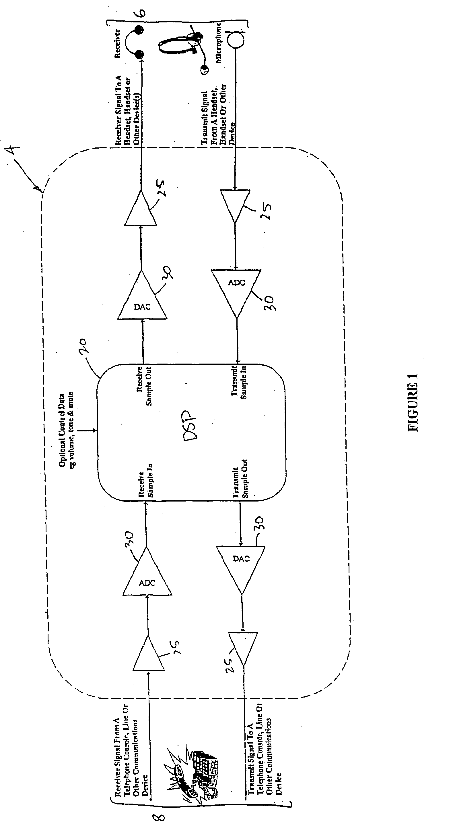
With reference to FIG. 1, preferred embodiments of the invention relate to an interface device 4 for communicating with a headset 6 and telephony device 8. The interface device 4 is powered by a power supply 10 (not shown), which is either separate or alternatively derived from telephony device 8.

The interface device 4 receives incoming telephony signals from the telephony device 8 in analogue form, digitally processes (in DSP 20, the operation of which is described below) these signals after D / A conversion 30 and forwards the signals on to the headset 6 (after reconversion to analogue form). The interface device 4 acts as a sound shield and screens out unwanted audio signals from interface device 8 in favour of normal voice signals. The interface device 4 also receives voice signals back from the headset 6 and passes these through to the telephony device 8 without processing by the digital signal processor (described (later). However, if a mute function of the interface device 4...


PUM


Abstract

A signal processing method including the steps of: receiving a first audio signal; detecting the presence of one or more shrieks within an audible frequency range of said audio signal; creating one or more filters to selectively attenuate the respective one or more shrieks within the audible frequency range; filtering the audio signal using the one or more filters; and transmitting the filtered audio signal to an audio telephone device.

Description

FIELD OF THE INVENTION The present invention relates generally to digital signal processing systems and methods for a telephony interface apparatus. More particularly, the invention relates to digital telephony apparatus interposed between a headset, handset or similar arrangement of electro-acoustic transducers and a telephony device for suppressing audio telephony signals which may be harmful to the human ear. BACKGROUND Occasionally, intense, unwanted signals accidentally occur within the telephone network. These signals are variously called acoustic shocks, audio shocks, acoustic shrieks, or high-pitched tones and will be referred to herein as shrieks or narrow-band signals. The exact source of an individual acoustic shock is usually unknown, but various sources are possible, such as alarm signals, signalling tones, or feedback oscillation. Although these narrow-band noises can affect anyone, people using a regular hand-held telephone can quickly move the phone away from thei...

Claims


Application Information

Patent Timeline
IPC IPC(8): H03G7/00H04M1/60H04M3/00H04M3/18H04M3/40H04M3/51
CPCH03G7/007H04M1/60H04M1/6033H04M3/5133H04M3/005H04M3/18H04M3/40H04M3/002
Inventor FISHER, MICHAEL JOHN AMIEL
Owner HEAR WORKS PTY LTD
Learn More