Mobile node, router, server and method for mobile communications under ip version 6 (ipv6) protocol

a mobile node and protocol technology, applied in the field of mobile nodes, routers, servers and methods for mobile communications under ip version 6 (ipv6) protocol, can solve the problems of increasing network load, increasing packet loss and delay, and affecting the service life of mobile nodes, so as to quickly eliminate the resource deficiency of home agents, the handover of mobile nodes is smooth and the effect of reducing network load

Inactive Publication Date: 2005-01-27
PANASONIC CORP
View PDF7 Cites 87 Cited by
  • Summary
  • Abstract
  • Description
  • Claims
  • Application Information

AI Technical Summary

Benefits of technology

As described above, according to the invention, even where the mobile node and the home agents are distant in space, network load can be relieved and h...

Problems solved by technology

Therefore, there is a drawback that the load over the network is increased by the control packets, such as binding update messages, to be sent by the mobile node to the home agent in order to register primary care-of addresses.
Meanwhile, where the distance increases between the home agent and the mobile node, it takes a l...

Method used


Image

  • Mobile node, router, server and method for mobile communications under ip version 6 (ipv6) protocol
  • Mobile node, router, server and method for mobile communications under ip version 6 (ipv6) protocol
  • Mobile node, router, server and method for mobile communications under ip version 6 (ipv6) protocol

Examples


embodiment 1

(Embodiment 1)

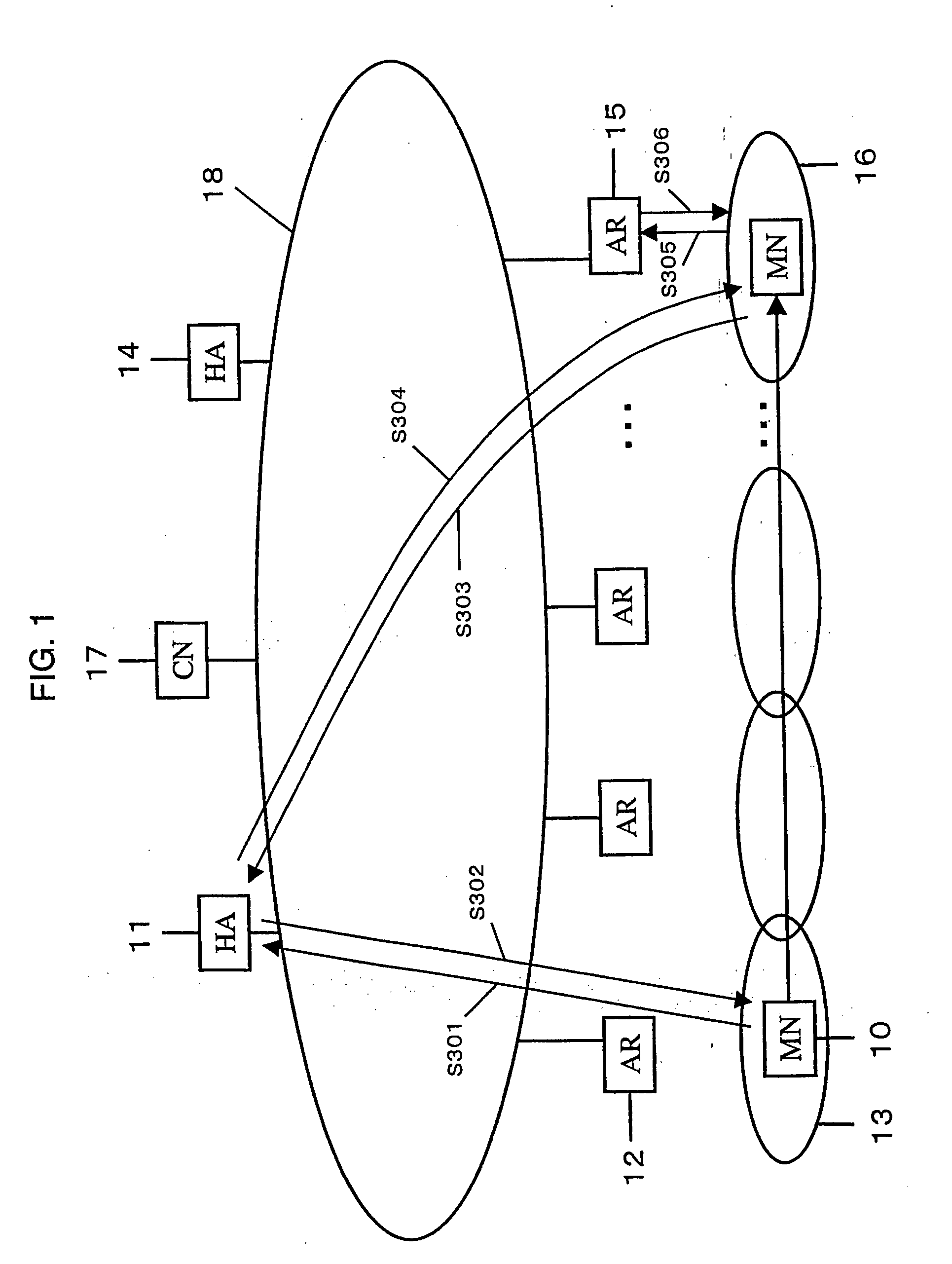
FIG. 1 is a configuration diagram of a mobile communication system in embodiment 1 of the present invention.

In FIG. 1, a mobile node 10 is a mobile communication terminal, and home agents 11, 14 are routers to which the mobile node 10 can be allowed to register the current care-of addresses. Access routers 12, 15 are routers accessible to the Internet to which the mobile node 10 can be allowed to access. Control ranges 13, 16 are respective ranges in which the access router 12, 15 can have communications. A correspondent node 17 is a communication terminal for communications with the mobile node 10, while an IP network 18 is an electric communication line over which an IP protocol is supported.

With the configuration of FIG. 1, the operation is explained in the below.

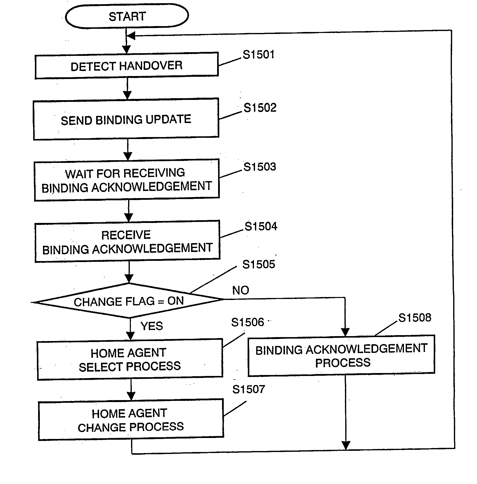
First, the mobile node 10 has an access to the access router 12 to get a care-of address, and then sends the home agent 11 a binding update message requesting a registration(step S301). The home agent...

embodiment 2

(Embodiment 2)

FIG. 13 is a configuration diagram of a mobile communication system in a second embodiment of the invention.

This is different from the mobile communication system of the first embodiment, in that a home agent information storing server 19 is provided to manage home agents.

The home agent information storing server 19 is stored with the addresses, managing prefixes, managing access routers 15, unoccupied resources and load of the home agents existing on the network, in a home agent information management table 3500 shown in FIG. 9A. In the case of requested from a home agent, access router 15 or mobile node 10, a suitable home agent is selected and notified from the home agent information management table 3500.

For example, as shown in FIG. 13, the access router 15 sends a home agent information request message 4550 to the home agent information storing server 19 in order to get the information about a home agent possessing the same in its control range (step S701)....

embodiment 3

(Embodiment 3)

Embodiment 3 of the invention is different from embodiment 1 in that a home agent decides a change of the home agent depending upon a status of its own unoccupied resource.

Embodiment 3 of the invention is explained by using FIG. 17. FIG. 17 is a network configuration diagram, which is different from embodiment 1 in that a home agent 20 is newly added.

In a configuration like FIG. 17, the operation is explained in the below. The mobile node 10 moves to have an access to a different access router 15 and gets a new care-of address, thereafter sending a home agent 14 a binding update message for registration (step S3201). The process up to this is similar to that of embodiment 1.

Next, the home agent 14, after receiving the binding update message 3950 (step S3201), makes sure of whether there is, in the binding cache, sufficient resource for generating a new entry to mobile node 10. In the case of resource deficiency, the home agent 14 sets a number representative of ...


PUM


Abstract

In a mobile communication system supported with IP version 6, a mobile node measures at least one of a hop number or communication delay time to a belonging home agent. When the result of measurement is equal to or greater than a predetermined value, registration deletion is requested to the belonging home agent while registration is requested to a new home agent. The belonging home agent deletes the registration of mobile node, and the new home agent registers the mobile node. This can reduce the load on an IP network and decrease data delay.

Description

TECHNICAL FIELD This invention relates to a method and apparatus for mobile communications supported with IP version 6 (hereinafter referred to as “IPv6”) in order for communications with another communication node through the use of the same address while the mobile node is connected with the other than the home link. BACKGROUND ART Conventionally, there are such mobile communication methods including a description in JP-A-2001-237764, for example. FIG. 33 shows a conventional mobile communication method described in JP-A-2001-237764. In FIG. 33, a radio station comprises hop-number information acquiring means 3301 for acquiring hop-number information from an accessible radio station, preferentially-accessing radio station selecting means 3302 for selecting preferentially-accessing radio stations, or relay points, out of accessible radio stations according to the hop-number information, and signal transfer means 3303 for transferring a transmission signal or a signal received fr...

Claims


Application Information

Patent Timeline
IPC IPC(8): H04L12/46H04L45/121H04L45/122H04L45/80H04W8/04H04W8/06H04W36/36H04W40/34H04W60/00H04W60/06H04W64/00H04W80/04
CPCH04L45/04H04L45/121H04L45/20H04W8/065H04L69/161H04W60/06H04W80/04H04L69/16H04L69/167H04W60/00
Inventor FUNABIKI, MAKOTOIKEDA, SHINKICHIMATSUMOTO, TAISUKEKIMURA, YASUNARIKOBAYASHI, HIROKAZU
Owner PANASONIC CORP
Why Eureka
Try Eureka