Network storage appliance with integrated redundant servers and storage controllers

a technology of storage controllers and network storage appliances, applied in the field of network storage, can solve the problems of inefficient use of storage devices, waste of remaining space, and difficulty in managing storage devices for potentially many computers in the network, and achieve the effect of reducing cost, space saving, and cost and space saving

Active Publication Date: 2005-01-27
DOT HILL SYST
View PDF62 Cites 119 Cited by
  • Summary
  • Abstract
  • Description
  • Claims
  • Application Information

AI Technical Summary

Benefits of technology

[0011] In one aspect, the present invention provides a network storage appliance that integrates a plurality of servers and a plurality of storage controllers into a single chassis. The storage controllers control transfers of data between the servers and storage devices controlled by the storage controllers. The servers and storage controllers comprise a plurality of field replaceable units (FRUs) that plug into a backplane also enclosed in the chassis. The FRUs are redundant such that any one of the FRUs may fail without incurring loss of availability of the data stored on the storage devices.
[0012] In another aspect, the FRUs comprise blade modules that plug into the backplane, thereby alleviating the need to open the chassis. In one embodiment, the blades may be removed and inserted from a single side of the chassis. The backplane includes local buses that interconnect the blades in a redundant, fault-tolerant fashion. In one embodiment, each blade connects to at least two local buses of the backplane.
[0016] An advantage of the storage appliance of the present invention is that it potentially reduces cost by reducing the number of enclosures needed and enables the servers and storage controllers to share common power and cooling systems within the enclosure. Also, space savings may be enjoyed by integrating the servers and storage controllers (what would heretofore typically have represented four distinct boxes) into a single chassis. The cost and space savings may be significant, particularly in an enterprise that incorporates many of the storage appliances since the cost and space savings would be multiplied. Yet another advantage is the potential increase in the reliability of the system, in particular by enclosing the network connections between the servers and storage controllers within the chassis and eliminating damage-prone inter-enclosure cabling between the servers and storage controllers. Still further, the network storage appliance presents an opportunity to improve the manageability of the server / storage controller combination over the discrete enclosure prior art implementation. This may be particularly advantageous due to the intertwined nature of the storage controller function and the server function when the server is performing a value-added storage function, such as a storage virtualization function.

Problems solved by technology

However, this model has certain disadvantages in an enterprise, such as a business or university, in which many computers are networked together, each having its own DAS.
One potential disadvantage is the inefficient use of the storage devices.
Each computer may only use a relatively small percentage of the space on its disk drive with the remainder of the space being wasted.
A second potential disadvantage is the difficulty of managing the storage devices for the potentially many computers in the network.
A third potential disadvantage is that the DAS model does not facilitate applications in which the various users of the network need to access a common large set of data, such as a database.
These disadvantages, among others, have caused a trend toward more centralized, shared storage in computer networks.
Consequently, the same types of problems that existed with the workstation DAS model existed again with the server DAS model.
The FRUs are redundant such that any one of the FRUs may fail without incurring loss of availability of the data stored on the storage devices.

Method used


Image

  • Network storage appliance with integrated redundant servers and storage controllers
  • Network storage appliance with integrated redundant servers and storage controllers
  • Network storage appliance with integrated redundant servers and storage controllers

Examples


Embodiment Construction

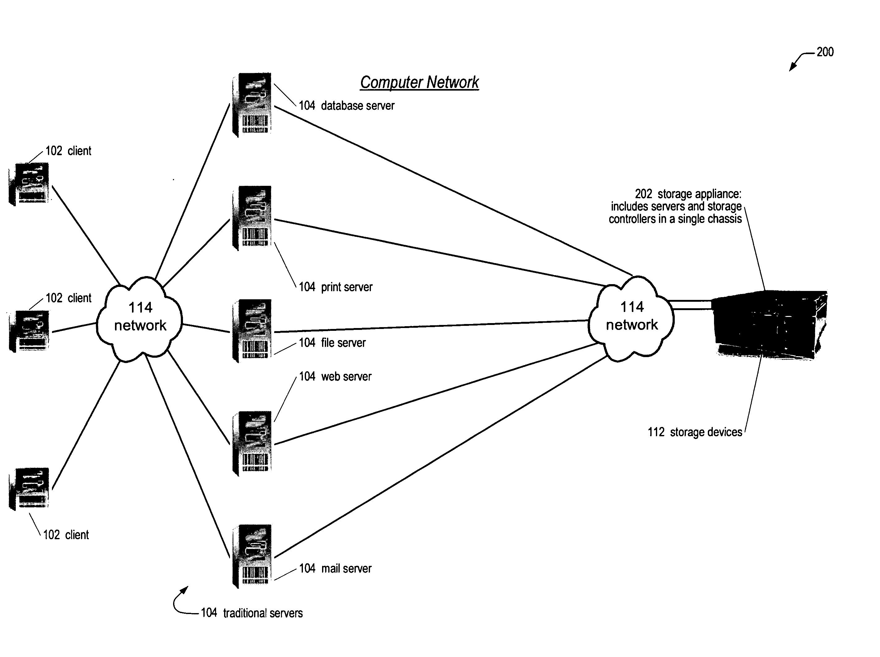
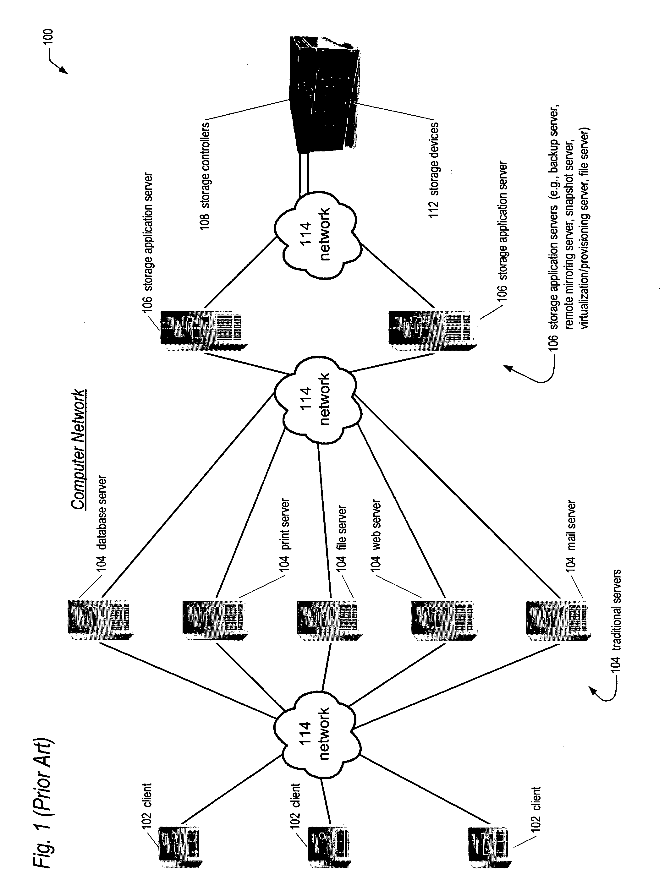
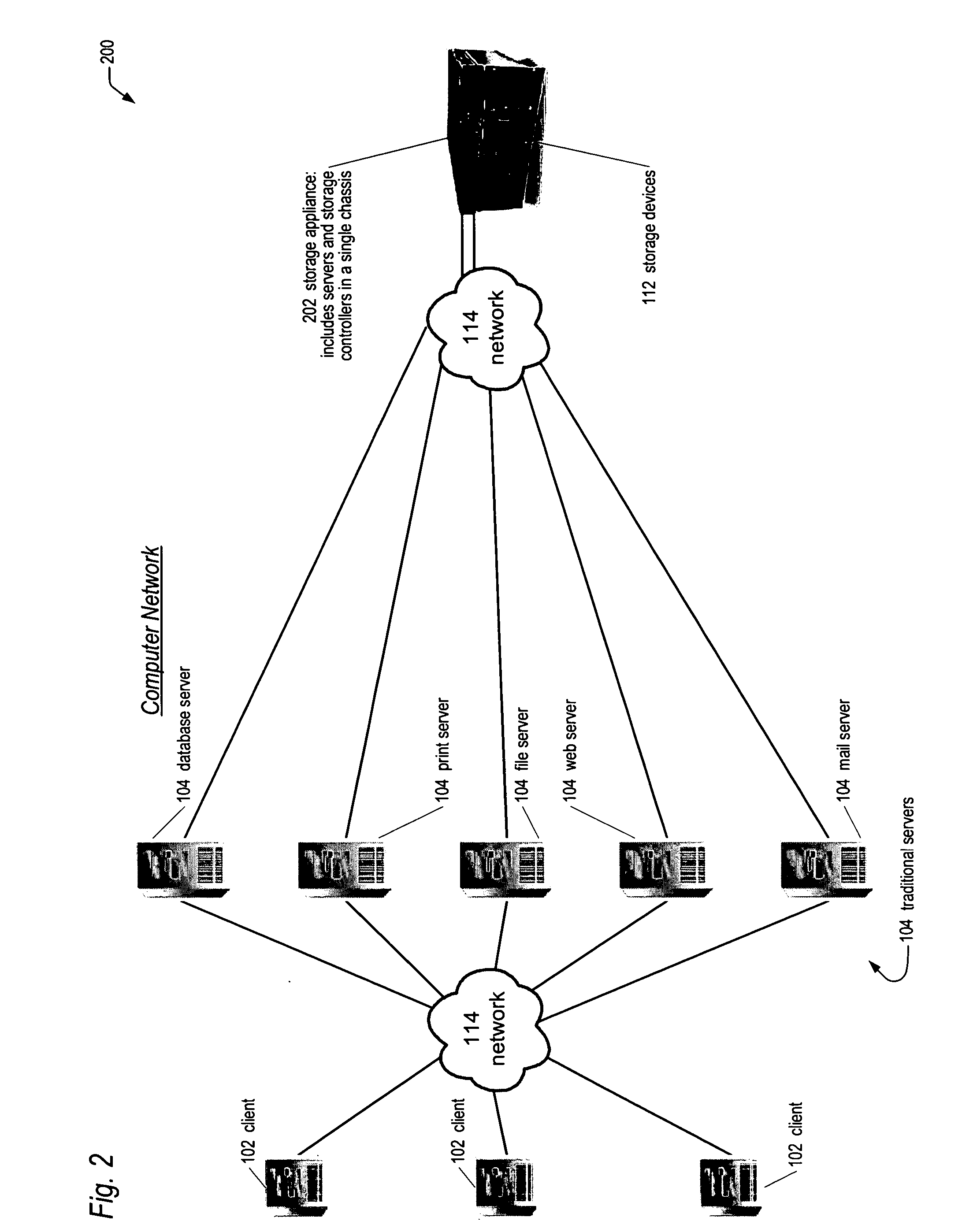
[0042] Referring now to FIG. 1, a diagram of a prior art computer network 100 is shown. The computer network 100 includes a plurality of client computers 102 coupled to a plurality of traditional server computers 104 via a network 114. The network 114 components may include switches, hubs, routers, and the like. The computer network 100 also includes a plurality of storage application servers 106 coupled to the traditional servers 104 via the network 114. The computer network 100 also includes one or more storage controllers 108 coupled to the storage application servers 106 via the network 114. The computer network 100 also includes storage devices 112 coupled to the storage controllers 108.

[0043] The clients 102 may include, but are not limited to workstations, personal computers, notebook computers, or personal digital assistants (PDAs), and the like. Typically, the clients 102 are used by end users to perform computing tasks, including but not limited to, word processing, datab...


PUM


Abstract

A network storage appliance is disclosed. The appliance includes a single chassis that encloses a plurality of servers and a plurality of storage controllers coupled together via a chassis backplane. The storage controllers control the transfer of data between the plurality of servers and a plurality of storage devices coupled to the storage controllers. The servers and storage controllers include a plurality of field replaceable unit (FRUs) hot-pluggable into the backplane such that any one of the FRUs may fail without loss of availability to the storage devices' data. In various embodiments, the chassis fits in a 19″ wide rack; is 1U high; the servers are standard PCs configured to execute off-the-shelf server applications and to facilitate porting of popular operating systems with little modification; the servers include disk-on-chip memory rather than a hard drive; local buses (e.g., PCIX) on the backplane interface the various FRUs.

Description

CROSS REFERENCE TO RELATED APPLICATION(S) [0001] This application claims the benefit of the following U.S. Provisional Application(s) which are incorporated herein by reference for all intents and purposes: Serial No.Filing DateTitle60 / 473355Apr. 23, 2003LIBERTY APPLICATION BLADE(CHAP. 0102)60 / 554052Mar. 17, 2004LIBERTY APPLICATION BLADE(CHAP.0111)[0002] This application is related to the following co-pending U.S. Patent Applications, all of which are being filed on the same day, and all having a common assignee and common inventors: Serial No.Filing(Docket No.)DateTitle      Apr. 23, 2004APPLICATION SERVER BLADE(CHAP.0106)FOR EMBEDDED STORAGEAPPLIANCE      Apr. 23, 2004NETWORK, STORAGE APPLIANCE,(CHAP.0107)AND METHOD FOR EXTERNALI-ZING AN INTERNAL I / O LINKBETWEEN A SERVER AND ASTORAGE CONTROLLERINTEGRATED WITHIN THESTORAGE APPLIANCE CHASSIS      Apr. 23, 2004APPARATUS AND METHOD FOR(CHAP.0108)STORAGE CONTROLLER TODETERMINISTICALLY KILL ONEOF REDUNDANT SERVERS INTE-GRATED WITHIN T...

Claims


Application Information

Patent Timeline
Patent Type & Authority Applications(United States)
IPC IPC(8): G06F3/06G06F7/00G06F9/00G06F11/00G06F11/20G06F12/00G06F13/14G06F15/16G06F15/173
CPCG06F3/0601G06F11/1456G06F11/2005G06F11/2007G06F11/201G06F11/1464G06F11/2035G06F11/2046G06F11/2051G06F11/2092G06F2003/0692G06F11/2028G06F3/0673
Inventor DAVIES, IAN ROBERTKALWITZ, GEORGE ALEXANDERPECONE, VICTOR KEY
Owner DOT HILL SYST
Why Eureka
Try Eureka