Compact micro-concentrator for photovoltaic cells

Active Publication Date: 2005-02-03
CREDIT SUISSE CAYMAN ISLANDS BRANCH
View PDF2 Cites 29 Cited by
  • Summary
  • Abstract
  • Description
  • Claims
  • Application Information

AI Technical Summary

Benefits of technology

[0008] Advantageously, the reflector array can be pressure formed or molded (herein referred to collectively as “formed”) as a single piece of plastic or other suitable material with alignment features provided for the photovoltaic receivers. The reflecting surfaces of

Problems solved by technology

While useful in concentrating solar energy, heretofore the use of the parabolic r

Method used


Image

  • Compact micro-concentrator for photovoltaic cells
  • Compact micro-concentrator for photovoltaic cells
  • Compact micro-concentrator for photovoltaic cells

Examples


Embodiment Construction

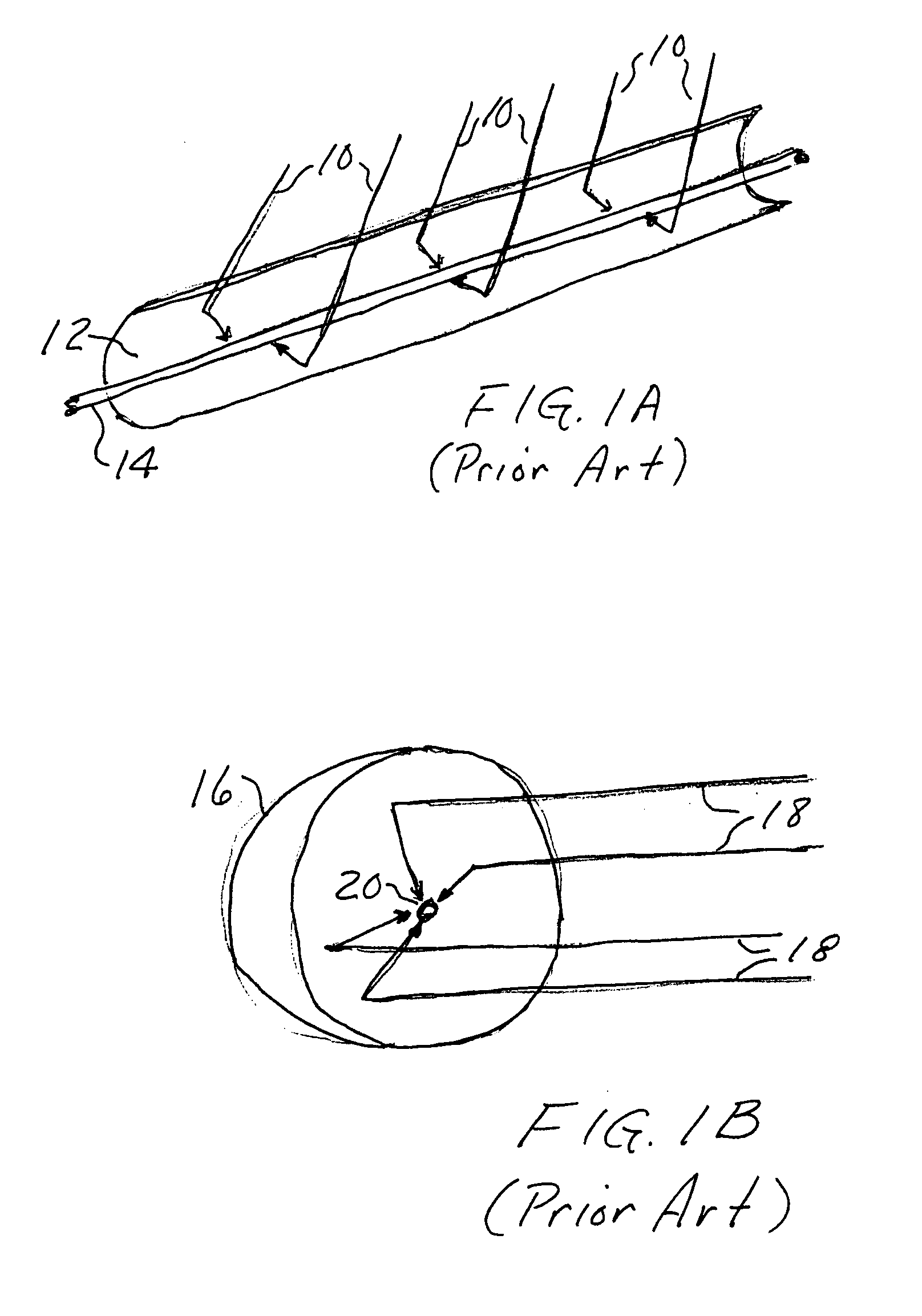
[0020] The parabolic reflector is a well-known device for receiving and directing energy to a central point, line or region, termed the “focus,” and similarly for transmitting energy radiating from the focus to the reflector and then transmitted outwardly in a beam that is parallel to the axis of the reflector. FIG. 1A is a perspective view of a prior art linear parabolic reflector in which energy such as radiant energy 10 striking the reflector 12 is directed to a line focus 14, for use in low concentration photovoltaic systems. Similarly, the parabolic dish 16 of FIG. 1B receives radiant energy and transmits the energy to a central point, or focus 20. Alternatively, energy radiating from the focus 20 to dish 16 can be transmitted outwardly in a beam 18 that is parallel to the axis of the dish.

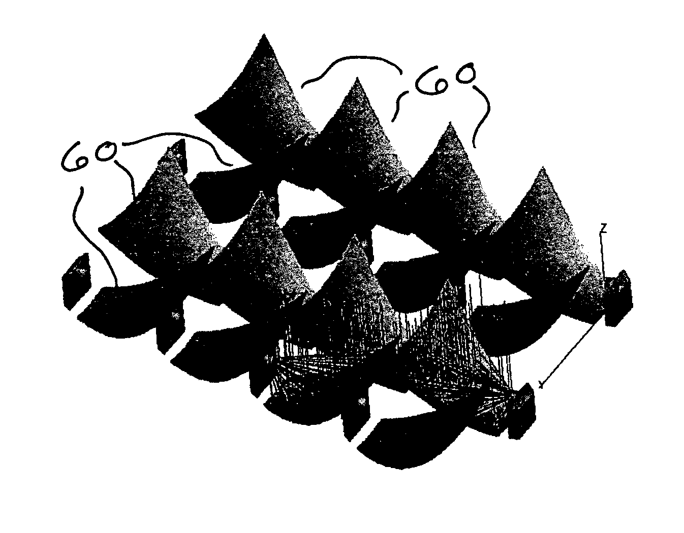
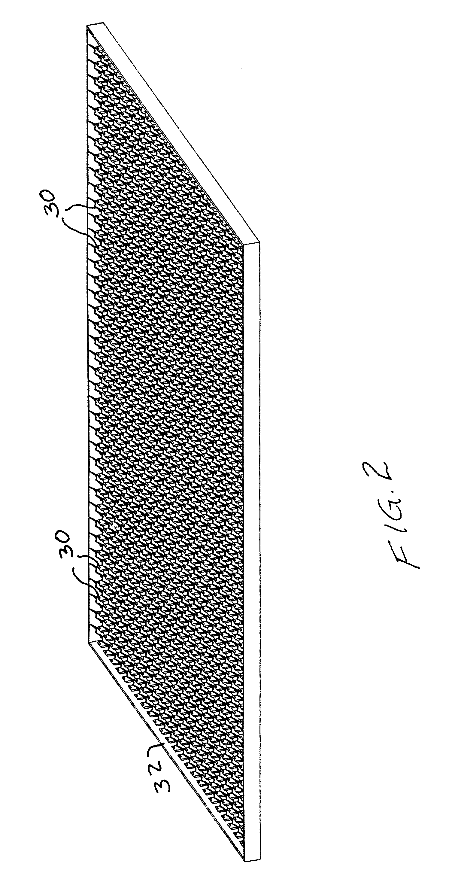
[0021] In accordance with the present invention, a compact micro-concentrator for photovoltaic cells, for example, is provided in which a plurality of radiation reflectors, each comprising a...


PUM


Abstract

A reflector array comprises a plurality of partial parabolic reflectors arranged in rows and columns with each reflector directing radiation to a receiver or from a transmitter located at the focus of the reflector. In a compact photovoltaic cell arrangement, each cell is shielded from direct radiation by the adjacent reflector. The reflectors can be formed as one unit with reflective material or with the reflecting surfaces coated with aluminum, silver, or other suitable reflecting material. A secondary reflector can be positioned at the focus of a reflector for directing radiation to a receiver or from a transmitter located at a more accessible location in the array.

Description

BACKGROUND OF THE INVENTION [0001] This invention relates generally to photovoltaic or solar cell arrays, and more particularly, the invention relates to energy concentration for use in such arrays. [0002] The use of photovoltaic cells for the direct conversion of solar radiation into electrical energy is well known, see Swanson, U.S. Pat. No. 4,234,352 for example. Briefly, the photovoltaic cell comprises a substrate of semiconductive material having a p-n junction defined therein. In the planar silicon cell the p-n junction is formed near a surface of the substrate which receives impinging radiation. Radiated photons create mobile carriers (holes and electrons) and the substrate which can be directed to an electrical circuit outside of the cell. [0003] In practical applications, photovoltaic cells are arranged in modules with the cells being serially connected to increase output voltage and with a plurality of serially connected cells connected in parallel to increase output curre...

Claims


Application Information

Patent Timeline
IPC IPC(8): H01L31/00
CPCH01L31/0547Y02E10/52
Inventor TERAO, AKIRAKRIPPENDORF, RALPH
Owner CREDIT SUISSE CAYMAN ISLANDS BRANCH
Why Eureka
Try Eureka