Reinforced impact beam

a technology of impact beams and reinforcements, applied in the direction of bumpers, shock absorbers, vehicular safety arrangments, etc., can solve the problems of affecting the integrity of the object, the impact beams are generally composite, and the impact beams are prone to break or in two parts, so as to improve the integrity, increase the resistance to impact, and improve the effect of energy absorption

Inactive Publication Date: 2005-02-03
VOESTALPINE POLYNORM PLASTICS
View PDF39 Cites 14 Cited by
  • Summary
  • Abstract
  • Description
  • Claims
  • Application Information

AI Technical Summary

Benefits of technology

[0005] It is an object of the present invention to provide an improved impact beam having increased resistance to impact. it is also an object of the invention to provide an impact beam having a high-energy absorption. It is an other object of the invention to provide an impact beam having an improved integrity during and after impact.
[0079] The polymer matrix is preferably bound to the metal cord by means of a mechanical bond. The polymer matrix may or may not be bound to the metal cords by means of a chemical bond. During a local impact, the polymer matrix, eventually by means of an embedding layer and a volume layer, distribute the local force over the full cord length. This results in a full use of the cord's energy absorption abilities hence the energy to be absorbed by other parts outside the beam is reduced and local breakage of the polymer matrix is postponed. The energy absorption of the cord is either through plastic stretching of the cord itself, through torsional deformation of the cord such as untwisting, or energy dissipation in the interface between cord and polymer layer due to friction when a relative movement of cord versus matrix is taking place. If the impact force is such that the local stresses in the polymer matrix exceed its breaking strength the polymer matrix will fall apart into pieces which still adhere to the metal cords. This falling apart will absorb a limited amount of impact energy, but after this falling apart, the metal cords may elongate to a larger extent and will be able to absorb to a large extent all impact energy possible until they break.
[0083] The impact beam as subject of the invention absorbs the impact energy and protects the other elements of the vehicle for damaging. The impact beam as subject of the invention also prevents the particles of the polymer matrix to damage peripheral elements of the vehicle, since the integrity of the impact beam after impact can be secured.

Problems solved by technology

Presently known composite impact beams in general have the disadvantage that they tend to break or in two parts at the location of impact, or into several small particles which are projected towards objects which are in the periphery of the impact beam.
This may cause further damage to these objects.

Method used


Image

  • Reinforced impact beam
  • Reinforced impact beam
  • Reinforced impact beam

Examples


Embodiment Construction

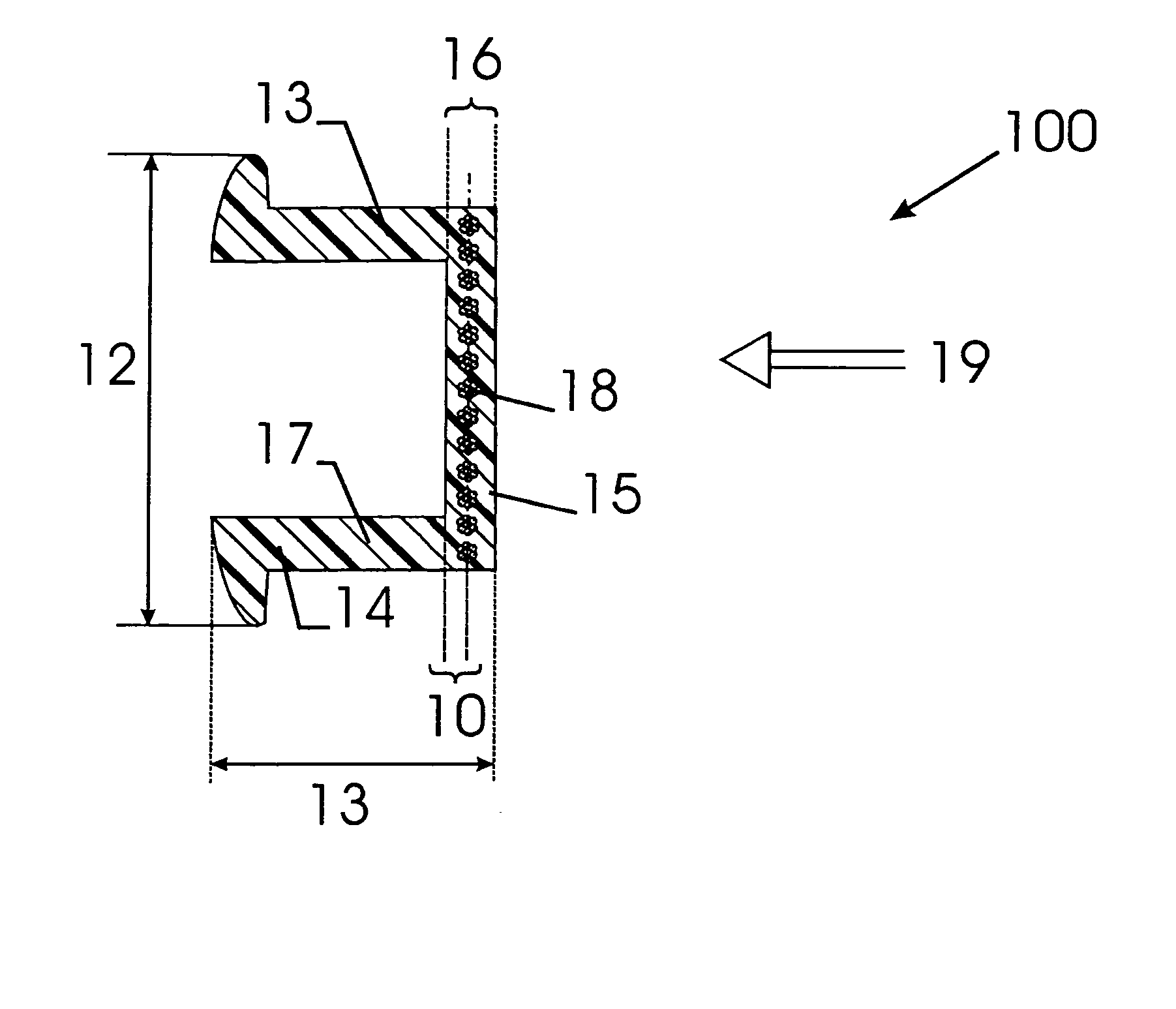
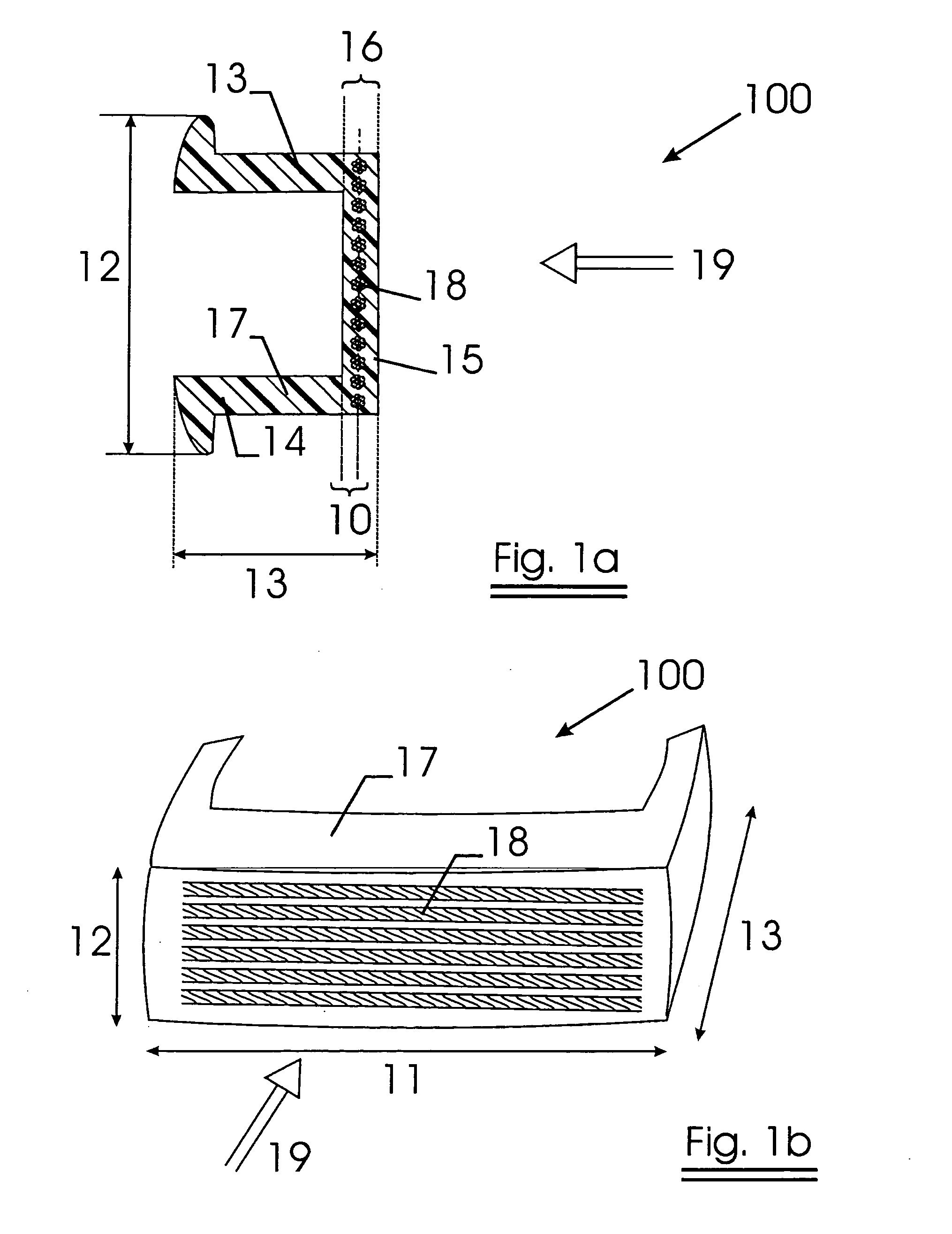
[0090] An impact beam as subject of the invention is schematically shown in FIG. 1a and FIG. 1b.

[0091] An impact beam 100 has a length 11, which is substantially larger than the height 12 and the thickness 13 of the impact beam 100. The embodiment as shown in FIG. 1 has a thickness that is provided by a pair of legs 14 and a main volume 15. The legs 14 may be used to fix the impact beam to other parts of the object to which it is to be mounted, whereas the main volume 15 (with its thickness 16) will absorb most of the impact energy provided by an impact in direction as indicated with arrow 19.

[0092] The main volume 15 and the legs 14 comprise a polymer matrix. In the main volume 15, metal cords 18 are present in a direction essentially parallel to the length 11 of the impact beam 100. Preferably all metal cord are present in one or more planes 10. The metal cords 18 used to provide the metal cord tape were 7×7 cords, being a core strand of a filament of 0.21 mm, round which 6 fila...


PUM

PropertyMeasurementUnit
diameteraaaaaaaaaa
optical diameteraaaaaaaaaa
elongationaaaaaaaaaa

Abstract

An impact beam having a polymer matrix and a metal reinforcing structure, the metal reinforcing structure including metal cords that can be made from metal elements having a diameter of 100 μm or more. The polymer matrix can include a thermoplastic material and / or a fiber material, and the metal can be steel, and the metal cords can be parallel to each other. The polymer matrix can include two or more layers that can be made from the same or different material, one of which can be positioned around the surface of the metal cords and can have a mechanical bond with the cord. The invention also includes a method of making the impact beam.

Description

[0001] The present application is a divisional of U.S. application Ser. No. 10 / 383,259, filed Mar. 7, 2003, the entire contents of which are incorporated herein by reference.FIELD OF THE INVENTION [0002] The present invention relates to impact beams and reinforcements, and a method to provide such impact beam. The invention further relates to the use of an impact beam for support of bumpers of vehicles or for impact reinforcing of parts of vehicles. BACKGROUND OF THE INVENTION [0003] Presently known composite impact beams comprise a polymer matrix, reinforced with glass fibers or other polymer fibers. An impact beam may also comprise metal parts, usually on the places where the impact beam receives compression load during impact. U.S. Pat. No. 5,290,079 gives an example of such impact beam. In U.S. Pat. No. 5,290,079 the impact beam also comprises a woven wire mesh, which is to improve the ductility and flexibility of the impact beam. [0004] Presently known composite impact beams in...

Claims


Application Information

Patent Timeline
Patent Type & Authority Applications(United States)
IPC IPC(8): B60R19/03B29C70/20B29C70/46B29C70/52B29C70/88B60R19/04B60R19/18F16F7/00
CPCB29C70/46B29C70/52B29C70/885B29K2995/0089B29L2031/3044Y10T29/4998B60R2019/1806B60R2019/1853Y10T29/49622Y10T29/49984B60R19/18
Inventor VAN DAMME, PETER A.M.CORSCADDEN, PAULDEKEYSER, WILLEM
Owner VOESTALPINE POLYNORM PLASTICS
Why Eureka
Try Eureka