Capacitance detector, method of detecting capacitance, and fingerprint sensor

a capacitance detector and capacitance detection technology, applied in the field of capacitance detectors, capacitance detection methods, fingerprint sensors, etc., can solve the problems of difficult to use each of the reference capacitance cr as a standard capacitance in the entire detecting system, and difficult to stably generate a reference capacitance cr

Inactive Publication Date: 2005-02-03
ALPS ALPINE CO LTD
View PDF7 Cites 79 Cited by
  • Summary
  • Abstract
  • Description
  • Claims
  • Application Information

AI Technical Summary

Benefits of technology

[0022] With this method, since the difference between the output voltage at charge and the output voltage at discharge is calculated, the effect of a discharge current caused by feedthrough, which is always superimposed on the capacitances at the intersections at a predetermined direction with respect to the charge and discharge currents, can offset.

Problems solved by technology

Accordingly, there are problems when the above detector is applied to, for example, an area sensor, in which a plurality of column lines and a plurality of row lines are arranged in a matrix, to detect minute capacitances near intersections of the column lines and the row lines.
Hence, it is difficult to stably generate a reference capacitance Cr, which is required to be substantially equal to the capacitance Cs to be detected, without errors.
With this structure, since variation is caused between the multiple reference capacitances Cr connected to the row lines intersecting with one column line, it is difficult to use each of the reference capacitances Cr as a standard capacitance in the entire detecting system.

Method used


Image

  • Capacitance detector, method of detecting capacitance, and fingerprint sensor
  • Capacitance detector, method of detecting capacitance, and fingerprint sensor
  • Capacitance detector, method of detecting capacitance, and fingerprint sensor

Examples


first embodiment

[0036] the present invention will now be described with reference to FIGS. 1 to 7.

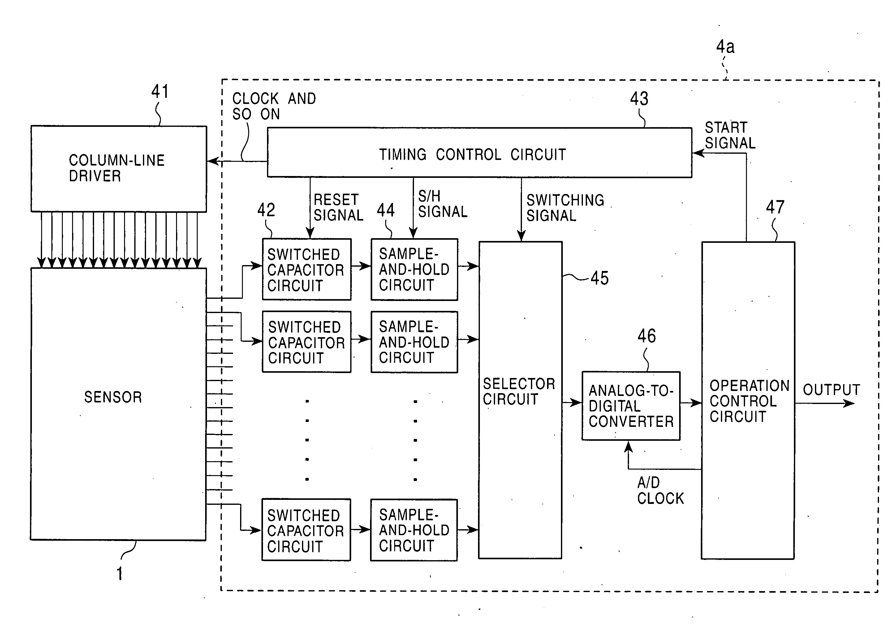
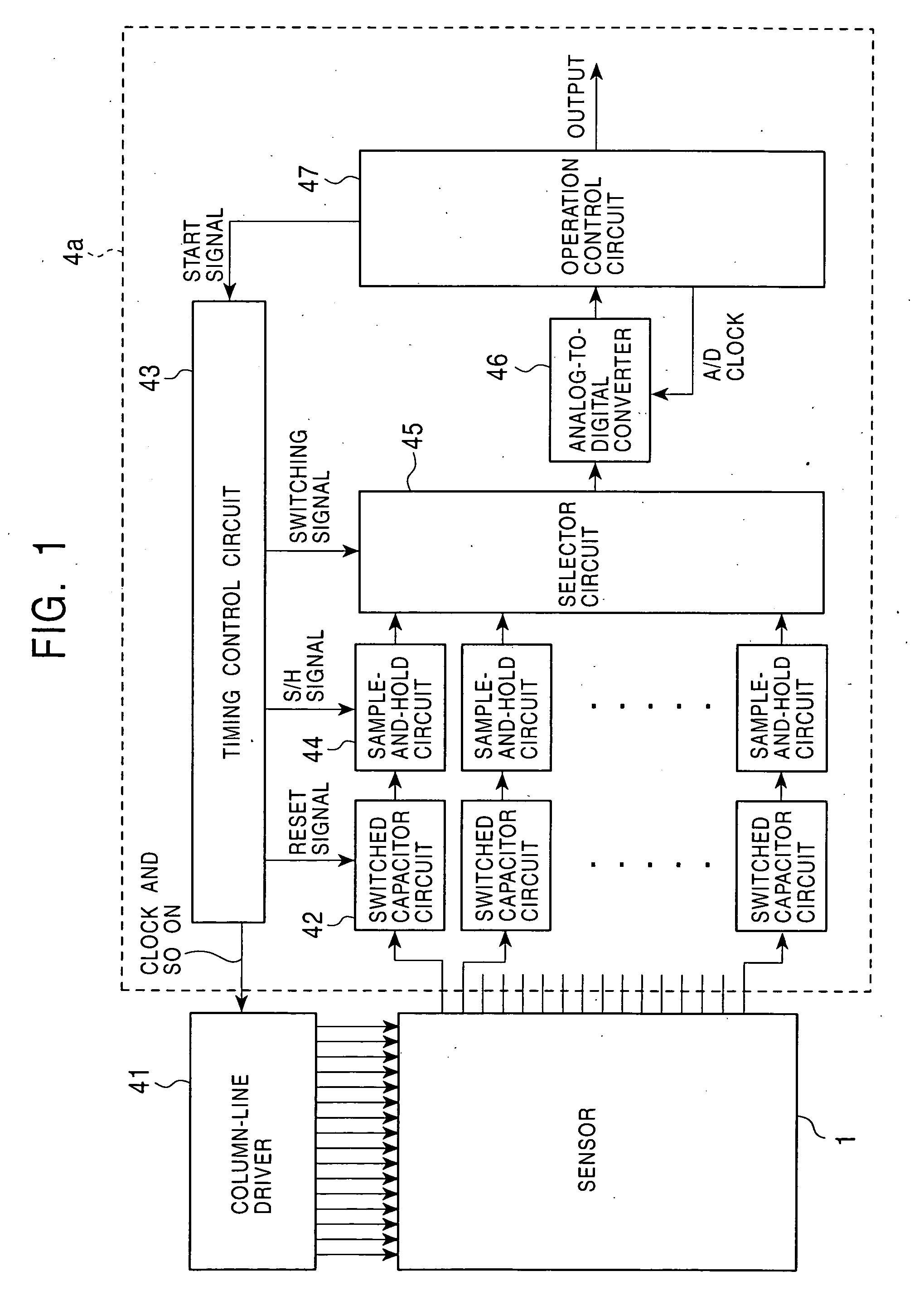
[0037]FIG. 1 is block diagram showing the structure of a capacitance detector 4a of the first embodiment. Referring to FIG. 1, a column-line driver 41 (column-line driving means) sequentially outputs signals that rise and fall at predetermined voltages to column lines of a sensor 1. While the column-line driver 41 does not output a signal, it maintains a ground potential. The signals output through row lines of the sensor 1 are supplied to the capacitance detector 4a.

[0038] When the capacitance detector 4a receives the output signals from the sensor 1, it detects a capacitance at each intersection of the column lines and the row lines. Internal functions of the capacitance detector 4a will now be described. A switched capacitor circuit 42 is connected to each row line. The switched capacitor circuit 42 outputs a voltage corresponding to a capacitance of each intersection of the row line connected ther...

second embodiment

[0051] the present invention will now be described.

[0052] Since the sensor 1 of the first embodiment has no reference data, detected values may vary when the structure of the sensor 1 is changed, particularly, when the structure of the sensor 1 is changed due to the variation in capacitance without a finger being pressed on the sensor 1. Accordingly, offset correction data is prepared in advance in the second embodiment.

[0053]FIG. 8 is a flowchart showing a process of correcting offset according to the second embodiment. Referring to FIG. 8, after the detection at all the intersections is completed and results of the operations described above are obtained, in Step Sa1, the process calculates a maximum amplitude from the maximum and minimum values among the detected values at all the intersections. In Step Sa2, the process determines whether the calculated maximum amplitude exceeds a reference value set in advance. If the determination is negative, the process determines that the d...

third embodiment

[0056] the present invention will now be described with reference to FIGS. 9 and 10.

[0057]FIG. 9 is a block diagram showing the structure of a capacitance detector 4b of the third embodiment. Referring to FIG. 9, the column-line driver 41 and the sensor 1 are the same as in the first embodiment shown in FIG. 1. However, the capacitance detector 4b of the third embodiment differs from the capacitance detector 4a of the first embodiment in that the capacitance detector 4b further includes a variable-gain amplifier 51 provided between the selector circuit 45 and the analog-to-digital converter 46. The gain level of the variable-gain amplifier 51 is adjusted based on a gain-level control signal output from the operation control circuit 47. As a characteristic of a fingerprint sensor, as long as the level of data at peaks can be determined relatively to the level of data at troughs, any difference in the absolute level of data causes no problem. Accordingly, the function of adjusting the...


PUM


Abstract

A capacitance detector, used in an area sensor having a matrix of detection lines, detects minute capacitances near intersections of a plurality of column lines and a plurality of row lines. The capacitance detector includes a column-line driver for outputting to the column lines a signal that rises in response to a first voltage and then falls in response to a second voltage; a row-voltage outputter for outputting a third voltage corresponding to a current for charging the capacitance at each of the intersections when the column lines are driven by the first voltage and for outputting a fourth voltage corresponding to a current for discharging the capacitance at each of the intersections when the column lines are driven by the second voltage; and a calculator for calculating the difference between the third voltage and the fourth voltage. The difference is calculated at each of the intersections.

Description

BACKGROUND OF THE INVENTION [0001] 1. Field of the Invention [0002] The present invention relates to a capacitance detector for detecting minute capacitances, a method of detecting capacitances, and a fingerprint sensor including the capacitance detector. [0003] 2. Description of the Related Art [0004] As fingerprint sensors, which appear most promising in biometrics (living-body authentication technology), pressure-sensitive capacitive sensors have been developed. In these pressure-sensitive capacitive sensors, two films are opposed to each other at a predetermined distance with an insulating film sandwiched therebetween. Column lines and row lines are formed on the respective surface of the two films at predetermined intervals. With this pressure-sensitive capacitive sensor, the form of the films vary in accordance with the form of the fingerprint of a finger that is placed on the sensor and the distance between the column lines and the row lines is varied in some portions. The fo...

Claims


Application Information

Patent Timeline
Patent Type & Authority Applications(United States)
IPC IPC(8): A61B5/117G01B7/28G01D5/241G01R27/26G06K9/00G06T1/00
CPCG06K9/0002G01D5/2417G06V40/1306G01R27/26
Inventor UMEDA, YUICHISAITO, JUNICHI
Owner ALPS ALPINE CO LTD
Why Eureka
Try Eureka