

Stage system including fine-motion cable unit, exposure apparatus, and method of manufacturing device
a technology of stage system and cable unit, which is applied in the field of stage system, can solve the problems of difficult to realize a stage movable in a long stroke in terms of machining ability, and the positioning accuracy of the fine-motion stage is decreasing, so as to achieve long strokes, high-precision positioning, and low cost.
- Summary
- Abstract
- Description
- Claims
- Application Information
AI Technical Summary
Benefits of technology
Problems solved by technology
Method used
Image

Examples
first embodiment
[0033] First Embodiment
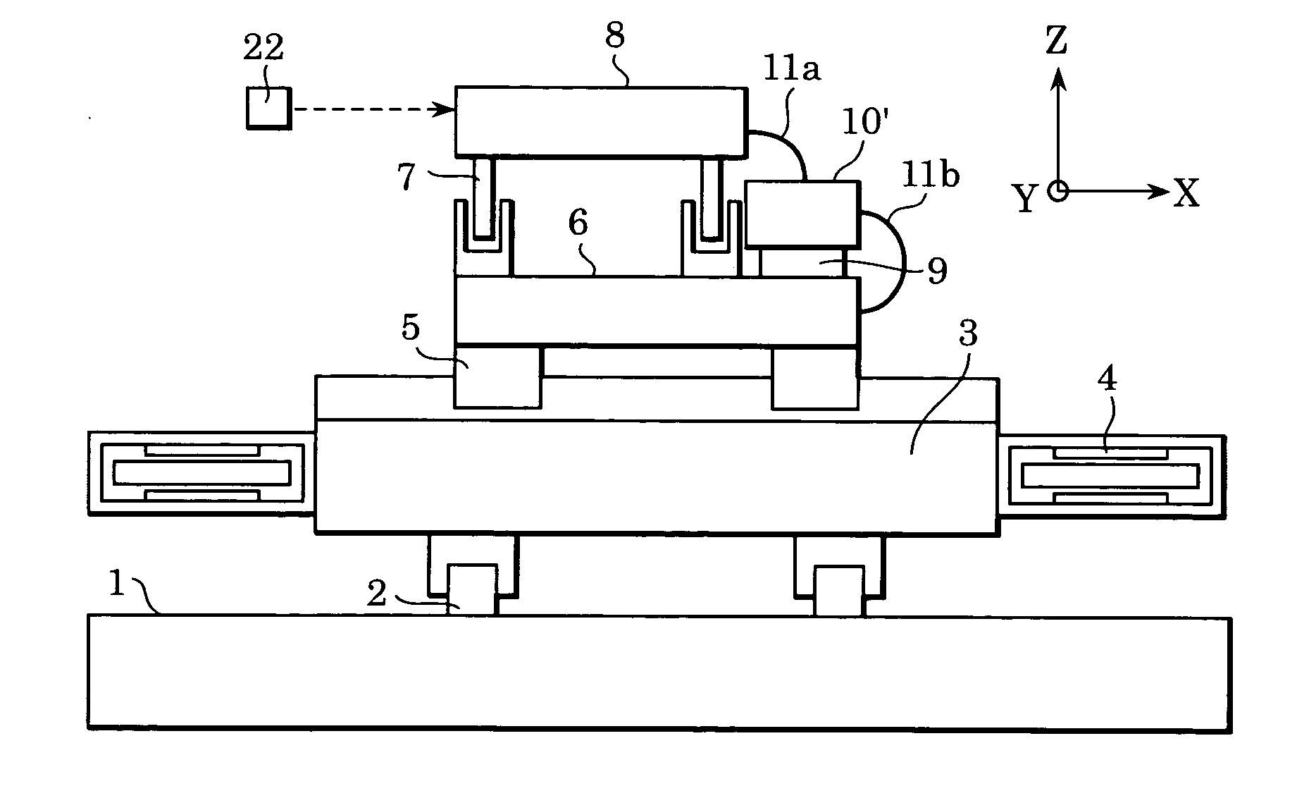
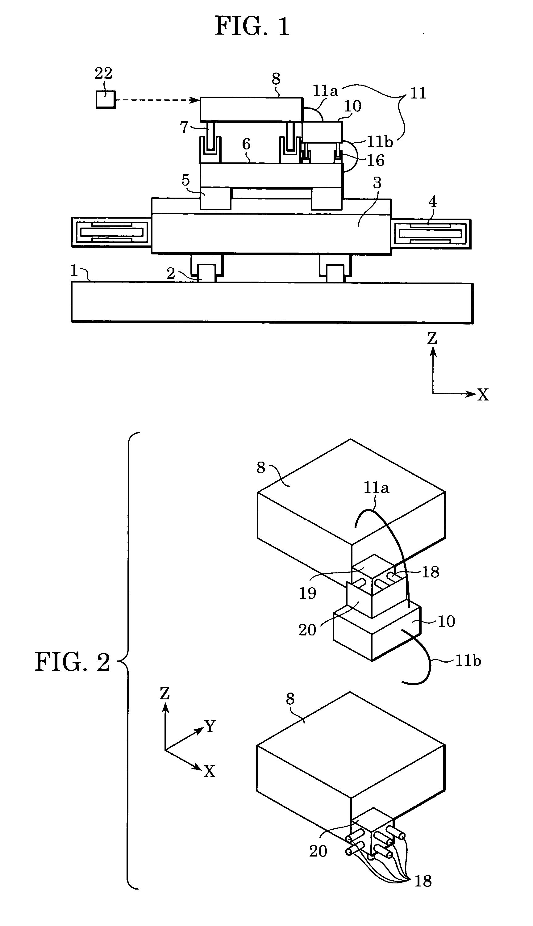
[0034]FIG. 1 shows a stage system according to a first embodiment of the present invention. In FIG. 1, a Y stage 3, being a coarse-motion stage in the Y direction, is guided by linear motor (hereinafter referred to as LM) guides 2 fixed on a base table 1 so as to be slidably supported in the Y direction. Y linear motors 4 are disposed on both sides of the Y stage 3 so that the Y stage 3 moves in a long stroke (coarse motion) in the Y direction.
[0035] LM guides 5 are disposed on the Y stage 3 to guide an X stage 6, being a coarse-motion stage in the X direction. Therefore, the X stage 6 is slidably supported by the LM guides 5 in the X direction with respect to the Y stage 3. The X stage 6 is equipped with an X linear motor (not shown) so as to be movable in a long stroke in the X direction.
[0036] In this embodiment, the LM guides 5 for the X stage 6 and the LM guides 2 for the Y stage 3 are of the LM guide type (e.g., rolling guides), which is inexpensive, h...
second embodiment
[0052] Second Embodiment
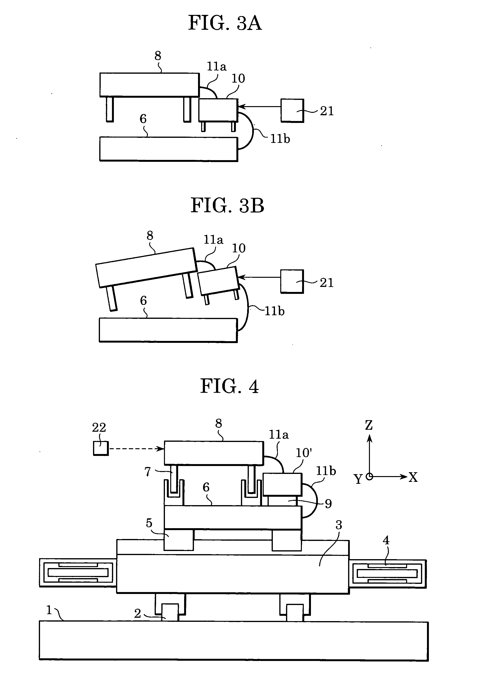
[0053]FIG. 4 shows an embodiment in which the fine-motion cable unit 10 of the first embodiment is made movable, finely, in three axial directions. The same reference numerals have been retained for similar parts, which have the same structures as those of the first embodiment, and explanations thereof are omitted.
[0054]FIGS. 5A to 5C show details of a fine-motion cable unit 10′, which is shown in FIG. 4. A magnet unit 10b is supported directly above the X stage 6 so as to be slidable in the X, Y, and θ directions. As illustrated in FIG. 5A, the magnet unit 10b, which is a fine-motion cable unit or a fine-motion cable stage, consists of yokes 13 / 14 and three pairs of magnets 12 that are magnetized in the Z direction and are fixed to the yokes 15. As shown in FIG. 5B, a coil plate 10a, which will be described below, is sandwiched between the magnets 12 in the vertical (Z) direction.
[0055] As shown in FIG. 5A, each pair of the magnets 12 consists of one magne...
third embodiment
[0060] Third Embodiment
[0061]FIG. 6 shows a third embodiment in which the stage system of the second embodiment is applied in a non-atmospheric environment, such as in a vacuum. A major difference in this embodiment is that an exhaust slot 17 is arranged around an air pad 9 supporting the magnet unit 10b of the fine-motion cable unit.
[0062] In FIG. 6, the same reference numerals have been retained for similar parts which have the same structures shown in FIG. 5C, and explanations thereof are omitted. In this embodiment, the exhaust slot 17 arranged around the air pad 9 is connected to an external pump with piping (not shown) therebetween. Gas emitted from the air pads 9 is retrieved by a pump (not shown) to prevent the gas from leaking to a vacuum atmosphere around the stage system.
[0063] Additionally, in order to avoid outgassing, a grease applicable to vacuum conditions may be used in the LM guides 5 (see FIG. 4) of the X stage 6, or surface treatment for vacuum conditions may b...
PUM
| Property | Measurement | Unit |
|---|---|---|
| distance | aaaaa | aaaaa |
| static pressure | aaaaa | aaaaa |
| routing distance | aaaaa | aaaaa |
Abstract
Description
Claims
Application Information