Carbon and electrospun nanostructures

a carbon nanotube and electrospun technology, applied in the field of carbon nanotubes, can solve the problems of low particularly expensive single-walled carbon nanotubes, and limited production of carbon nanotubes, e.g., swnt and mwnt, and achieve the effect of increasing the production rate of carbon nanotubes

Inactive Publication Date: 2005-02-03
PHYSICAL SCI
View PDF15 Cites 55 Cited by
  • Summary
  • Abstract
  • Description
  • Claims
  • Application Information

AI Technical Summary

Benefits of technology

[0005] The present invention also includes a nanofiber produced by electrospinning a polymer solution. For example, the invention also includes a nanofiber comprising: (a) about 87 to about 99 weight percent of a thermoset polymer, such as a polyacrylonitrile or polyimide. The nanofiber can include greater than zero and less than about 7 weight percent polyaniline emeraldine base or a salt thereof; greater than zero and less than about 5 weight percent i...

Problems solved by technology

A major impediment to the development of materials based on carbon nanostructure technology, particularly SWNT and MWNT carbon nanotube technology, has been the relatively high cost and low production rates of carbon nanostructures such as SWNT and MWNT.
Pure single wall carbon nanotubes are particularly expensive and typically have low production rates.
The production of carbon nan...

Method used


Image

  • Carbon and electrospun nanostructures
  • Carbon and electrospun nanostructures
  • Carbon and electrospun nanostructures

Examples


example

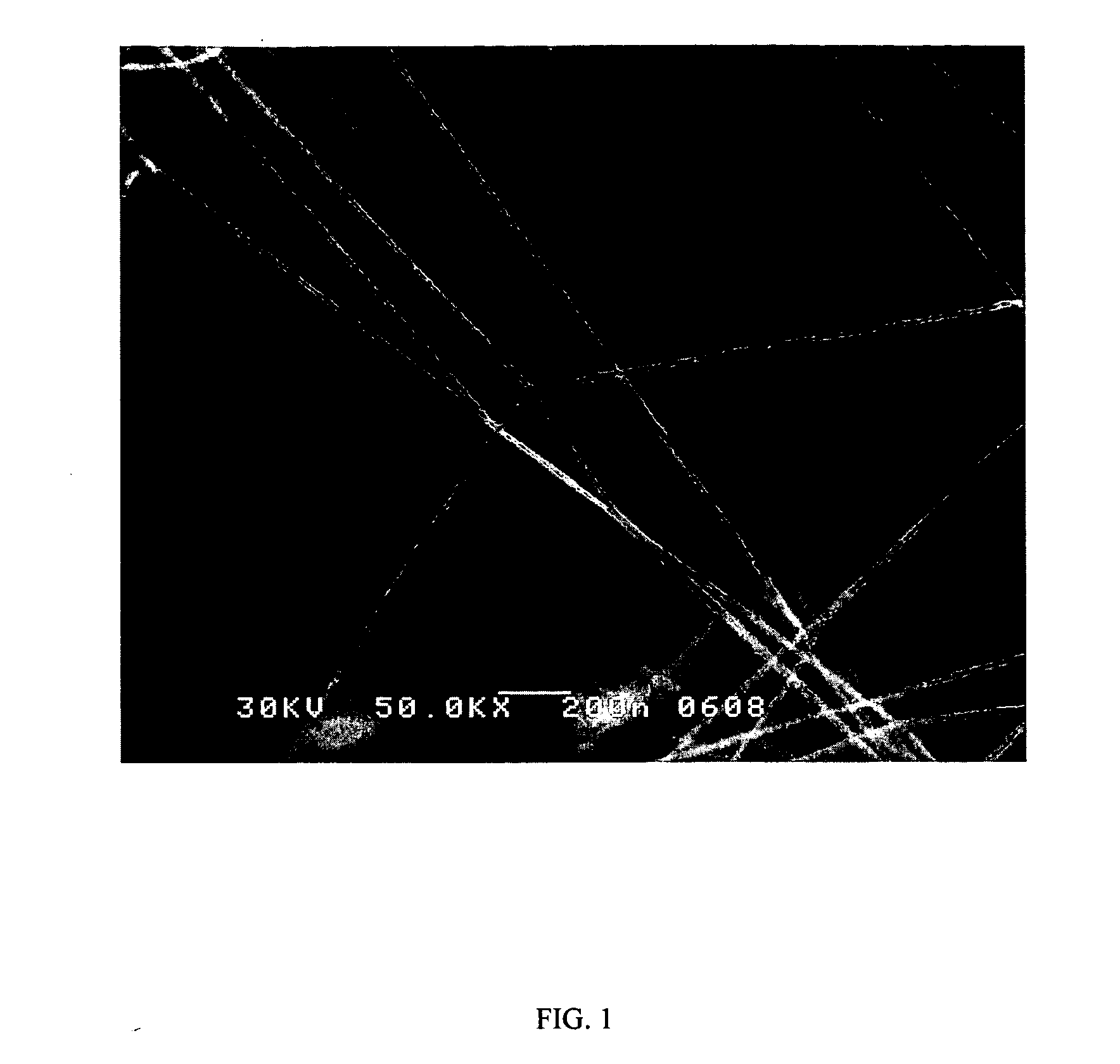
[0020] A solution was formed in N,N-dimethylformamide of 4% by weight low molecular weight polyacrylonitrile (PAN) (Sigma-Aldrich Co.; Molecular Weight: 86,200 daltons), 0.4% by weight polyaniline (PANi) emeraldine base (Organic Technologies, Lot# 17735NC), and 0.1% by weight iron chloride (FeCl2). The solution was ultrasonicated until all of the polyacrylonitrile had dissolved, typically about 8 hours. The solution was electrospun to form nanofibers using parallel plate geometry with a 5 centimeter plate separation, a potential of 15 kilovolts (kV) DC, a solution flow rate of 0.25 milliliters / hour and a current of 160 nanoamperes (nA). FIG. 1 is an FESEM of a 15 nm polyarcrylonitrile precursor to a multi-wall nanotube formed by the method of the invention. The nanofibers were then heated in air at 310° C. for 20 minutes and then placed in a tube furnace with a oxygen-free nitrogen purge, heated to 1,400° C. at 10° C. / min and pyrolized for 5 minutes at 1,400° C. The furnace was then...


PUM

PropertyMeasurementUnit
Fractionaaaaaaaaaa
Percent by massaaaaaaaaaa

Abstract

The present invention is directed to the production of nanostructures, e.g., single wall carbon nanotubes (“SWNT”) and/or multi-wall carbon nanotubes (“MWNT”), from solutions containing a polymer, such as polyacrylonitrile (PAN). In particular, the invention is directed to the production of nanostructures, for example, SWNT and/or MWNT, from mixtures, e.g., solutions, containing polyacrylonitrile, polyaniline emeraldine base (PANi) or a salt thereof, an iron salt, e.g., iron chloride, and a solvent. In one embodiment, a mixture containing polyacrylonitrile, polyaniline emeraldine base or a salt thereof, an iron salt, e.g., iron chloride, and a solvent is formed and the mixture is electrospun to form nanofibers. In another embodiment, the electrospun nanofibers are then oxidized, e.g., heated in air, and subsequently pyrolyzed to form carbon nanostructures.

Description

RELATED APPLICATION [0001] This application claims the benefit of U.S. Provisional Application No. 60 / 484,335, filed Jul. 2, 2003. The entire teachings of the above application are incorporated herein by reference.GOVERNMENT SUPPORT [0002] The invention was supported, in whole or in part, by grant MDA972-02-C-0029 from the Defense Advanced Research Projects Agency (DARPA). The Government has certain rights in the invention.BACKGROUND OF THE INVENTION [0003] Carbon nanostructures, for example, single wall carbon nanotubes (“SWNT”) and multi-wall carbon nanotubes (“MWNT”), have attracted significant interest in recent years for their potentially unique electrical and mechanical properties. A major impediment to the development of materials based on carbon nanostructure technology, particularly SWNT and MWNT carbon nanotube technology, has been the relatively high cost and low production rates of carbon nanostructures such as SWNT and MWNT. Pure single wall carbon nanotubes are particu...

Claims


Application Information

Patent Timeline
IPC IPC(8): C01B31/02D01D5/00D01F9/22
CPCB82Y30/00B82Y40/00C01B31/0233C01B2202/02Y10T428/30D01D5/0038D01F9/22Y10S977/842C01B2202/06C01B32/162
Inventor LENNHOFF, JOHN D.
Owner PHYSICAL SCI
Why Eureka
Try Eureka