Internet protocol telephony security architecture

a security architecture and protocol telephony technology, applied in the field of internet protocol telephony, can solve the problems of unauthorized access to the communication system in an unauthorised manner, the efforts of unauthorized users, and the relatively unsecured network that potentially provides high value to unauthorized users

Inactive Publication Date: 2005-02-03
GOOGLE TECH HLDG LLC
View PDF9 Cites 78 Cited by
  • Summary
  • Abstract
  • Description
  • Claims
  • Application Information

AI Technical Summary

Benefits of technology

[0011] A secure Internet Protocol (IP) telephony system, apparatus, and methods are disclosed. Communications over an IP telephony system can be secured by securing communications to and from a Cable Telephony Adapter (CTA). The system can include one or more CTAs, network servers, servers configured as signaling controllers, key distribution centers (KDC), and can include gateways that couple the IP telephony system to a Public Switched Telephone Network (PSTN). Each CTA can be configured as secure hardware and can be configured with multiple encryption keys that

Problems solved by technology

Some users may attempt to access the communication system in an unauthorized manner in an attempt to receive the benefits of the communication system without the corresponding cost.
In contrast, a relatively unsecured network that potentially provides high value to unauthorized users may constantly be targeted by unauthorized users.
Basic phone service is typically of lower value and is not often the efforts of unauthorized users.
However, long distance service provided by the phone system has a much higher value and thus, is the goal of many attacks to the system.
The theft of network services can occur through many means.
However, unauthorized system access is gained typically through the use of hardware clones or protocol attacks.
Communication systems such as wireless telephone sy

Method used


Image

  • Internet protocol telephony security architecture
  • Internet protocol telephony security architecture
  • Internet protocol telephony security architecture

Examples


Embodiment Construction

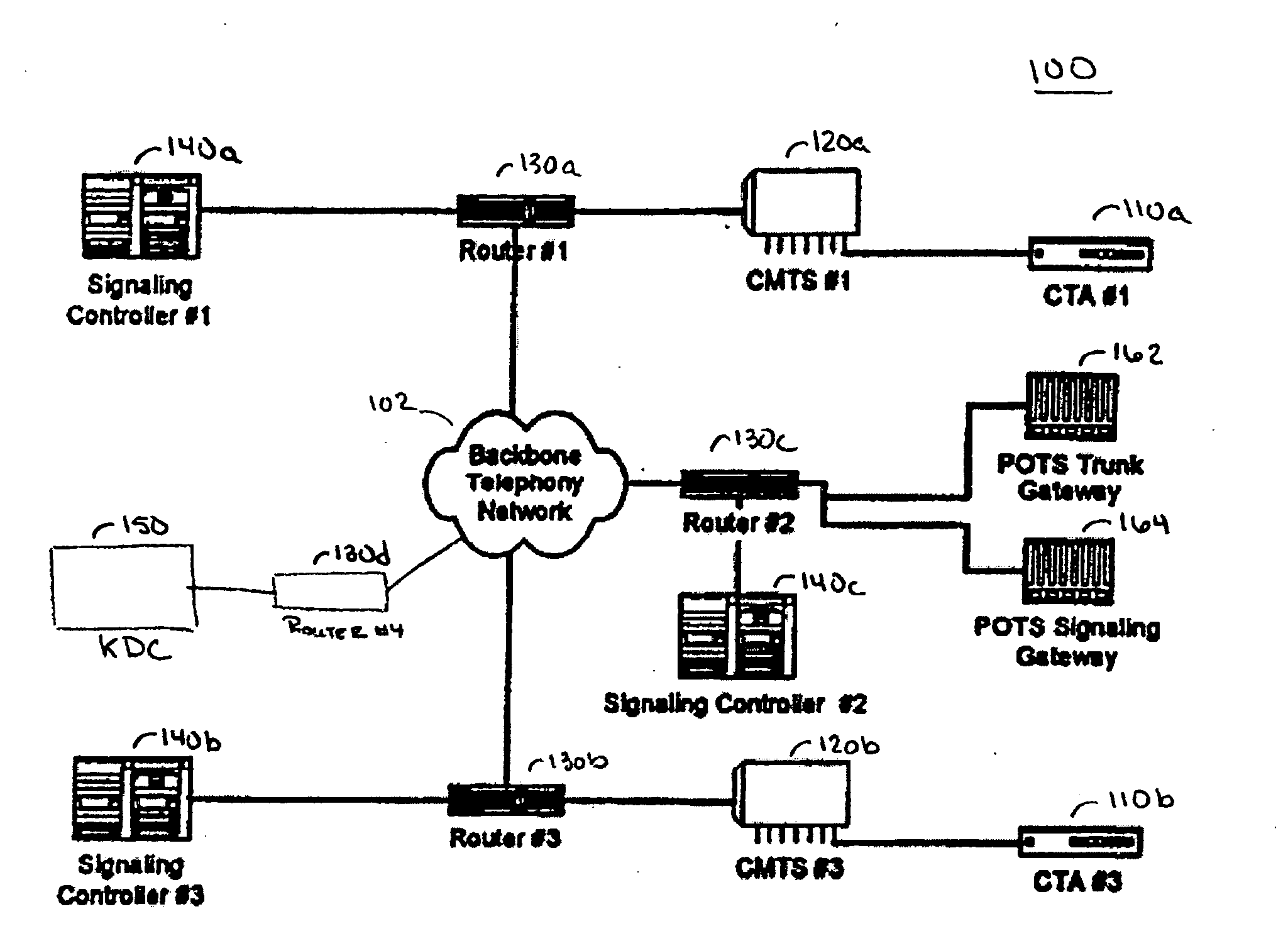
[0030] A secure network architecture for IP telephony is disclosed. The secure IP telephony architecture can be implemented in a secure IP telephony system, apparatus for use in a secure system, and methods embodied within the secure system. The secure IP telephony system is disclosed in relation to an IP telephony system implemented in a Hybrid Fiber Coax (HFC) system. However, the secure system is not limited to an HFC system and other system implementations are possible.

[0031] The secure system includes a number of encryption keys that are distributed between the various network elements in the secure IP telephony system. The encryption keys are used to ensure the security of signaling messages as well as the security of the bearer channel messages.

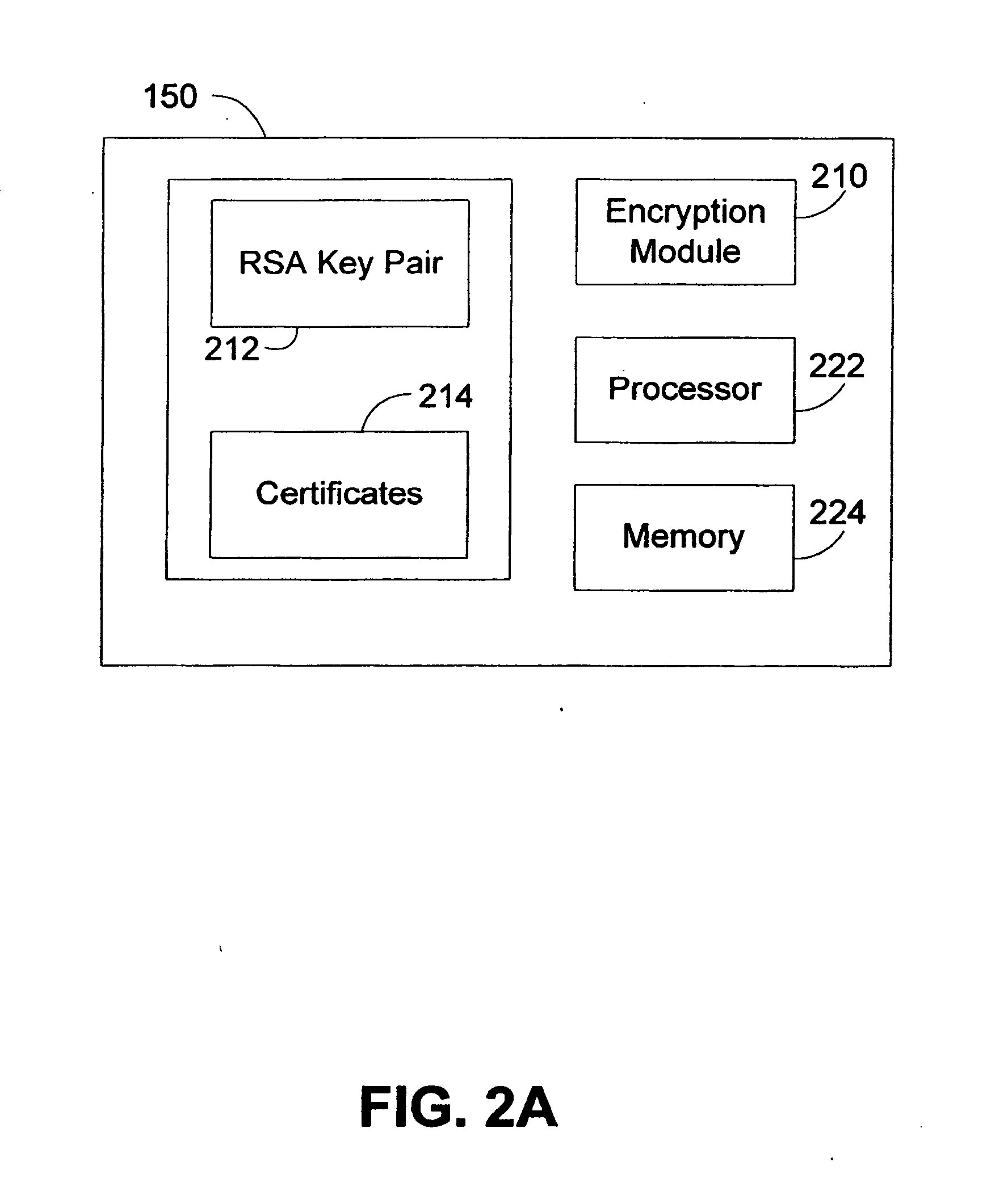
[0032] A Key Distribution Center (KDC) distributes symmetric encryption keys to the network elements using authenticated public key encryption. The use of public key encryption with authentication allows for nearly limitless scaling ...


PUM


Abstract

A secure Internet Protocol (IP) telephony system, apparatus, and methods are disclosed. Communications over an IP telephony system can be secured by securing communications to and from a Cable Telephony Adapter (CTA). The system can include one or more CTAs, network servers, servers configured as signaling controllers, key distribution centers (KDC), and can include gateways that couple the IP telephony system to a Public Switched Telephone Network (PSTN). Each CTA can be configured as secure hardware and can be configured with multiple encryption keys that are used to communicate signaling or bearer channel communications. The KDC can be configured to periodically distribute symmetric encryption keys to secure communications between devices that have been provisioned to operate in the system and signaling controllers. The secure devices, such as the CTA, can communicate with other secure devices by establishing signaling and bearer channels that are encrypted with session specific symmetric keys derived from a symmetric key distributed by a signaling controller.

Description

CROSS-REFERENCES TO RELATED APPLICATIONS [0001] This application is a continuation of U.S. application Ser. No. 09 / 546,900 filed Apr. 10, 2000, entitled INTERNET PROTOCOL TELEPHONE SECURITY ARCHITECTURE, which claims the benefit of U.S. Provisional Application 60 / 128,772, filed Apr. 9, 1999, entitled INTERNET PROTOCOL TELEPHONE SECURITY ARCHITECTURE, each of which is hereby incorporated herein by reference in its entirety.BACKGROUND OF THE INVENTION [0002] The disclosure relates to Internet Protocol telephony. More particularly, the disclosure relates to security in an Internet Protocol telephony network. [0003] Communication systems, particularly communication networks enabled for public access, are configured to provide remote communications for users connected to the system. System operators may bill system users based in part on a perceived value of the communication services provided by the network or based in part on a level of network resources engaged in supporting a user co...

Claims


Application Information

Patent Timeline
IPC IPC(8): G06F1/00G06F12/14G06F21/00H04L9/32H04L29/06
CPCG06F12/1408H04L9/3263G06F2207/7219G06F2211/008G06F2221/2129H04L29/06027H04L63/0435H04L63/0442H04L63/061H04L63/062H04L63/0807H04L63/12H04L65/1043H04L9/083H04L9/0841H04L9/3213G06F21/606H04L65/1101
Inventor SPRUNK, ERIC J.MORONEY, PAULMEDVINSKY, ALEXANDERANDERSON, STEVEN E.FELLOWS, JONATHAN A.
Owner GOOGLE TECH HLDG LLC
Why Eureka
Try Eureka