Floor cleaning apparatus with control circuitry

a technology of control circuits and floor cleaning, applied in the direction of vehicle cleaning, photosensitive materials, instruments, etc., can solve the problem of severe damage to the coating surfa

Inactive Publication Date: 2005-02-10
JOHNSONDIVERSEY INC
View PDF66 Cites 125 Cited by
  • Summary
  • Abstract
  • Description
  • Claims
  • Application Information

AI Technical Summary

Benefits of technology

[0006] The present inventors have discovered that performing the burnishing operation with one or more of the sweeping and / or scrubbing operations is advantageous. Combining the scrubbing and burnishing operations, in a unitary, coordinated method or system so that the operations are performed serially, but closely spaced in time, is particularly desirable and provides certain advantages not previously achieved or recognized.
[0007] In addition, a preferred embodiment of the present invention includes at least scrubbing and burnishing, and most preferably all three operations, in a single unitary device with logical electronic and mechanical controls that allow a single operator to easily manipulate all of activities of the floor cleaning operations simultaneously. This permits all three traditional operations to be performed with a single pass of the floor cleaning device over a given floor area. Advantages include the saving of labor and time as well as ensuring that the burnishing operation will never be performed on an unclean floor which could result in forcing the soil into the surface causing discoloration or severe damage to the coating surface. More surprisingly, the present system provides enhanced performance compared to the conventional operations performed serially at widely spaced intervals using separate devices. More particularly, the burnishing operation provides enhanced results, such as increased gloss, when performed closely following the scrubbing operation.
[0020] The scrubber includes a member which is mounted for movement from a first position to a second position. In its first position, the member prevents cleaning liquid from the scrubber brush to fall on the floor. In its second position, the member prevents the cleaning liquid from the scrubber brush to splash against at least a portion of the cleaner. The member extends along the length of the scrubber brush and is rotatable between the first and second positions around a second axis substantially parallel to the axis of rotation of the scrubber brush.
[0025] In another general aspect, the invention features a floor cleaner for cleaning a floor which includes: a scrubber for wetting and cleaning the floor; and a member being mounted for movement from a first position to a second position, where in the first position the member prevents cleaning liquid from the scrubber brush to fall on the floor and in the second position the member prevents the cleaning liquid from the scrubber brush to splash against at least a portion of the cleaner.

Problems solved by technology

Advantages include the saving of labor and time as well as ensuring that the burnishing operation will never be performed on an unclean floor which could result in forcing the soil into the surface causing discoloration or severe damage to the coating surface.
Because these coatings can be damaged or marked during use, such surfaces are typically maintained by periodic sweeping, wet scrubbing and / or burnishing.

Method used


Image

  • Floor cleaning apparatus with control circuitry
  • Floor cleaning apparatus with control circuitry
  • Floor cleaning apparatus with control circuitry

Examples


Embodiment Construction

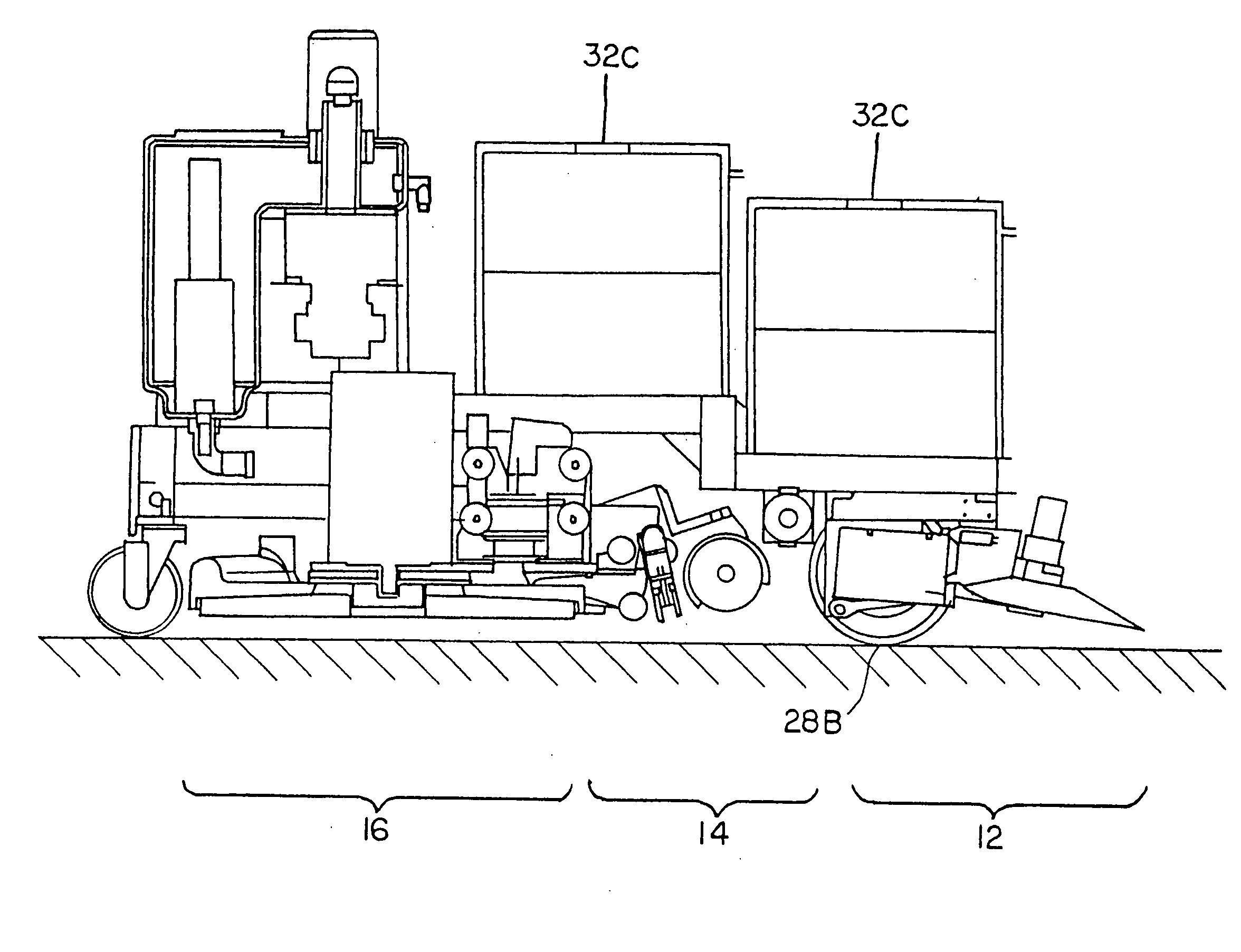
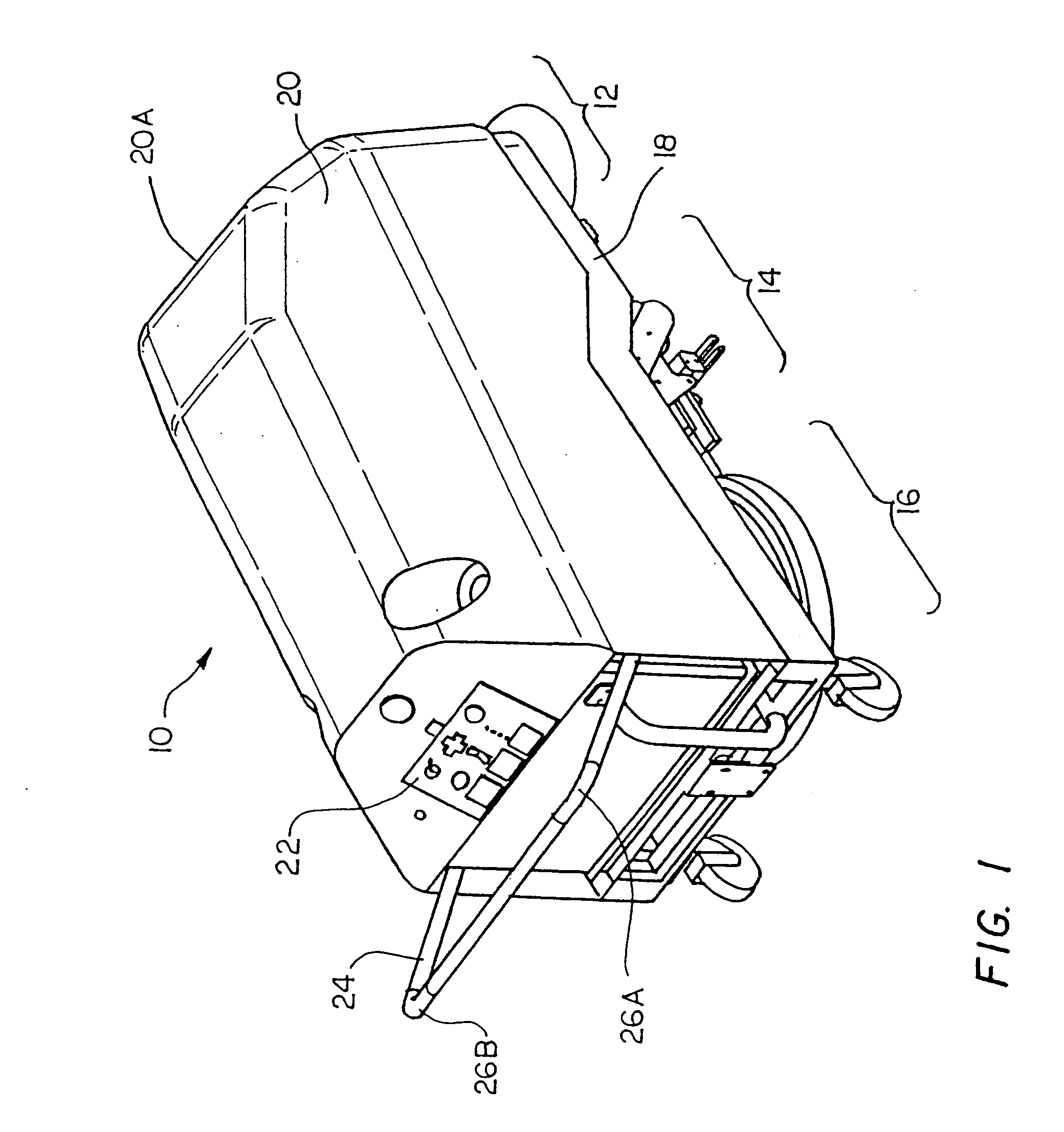
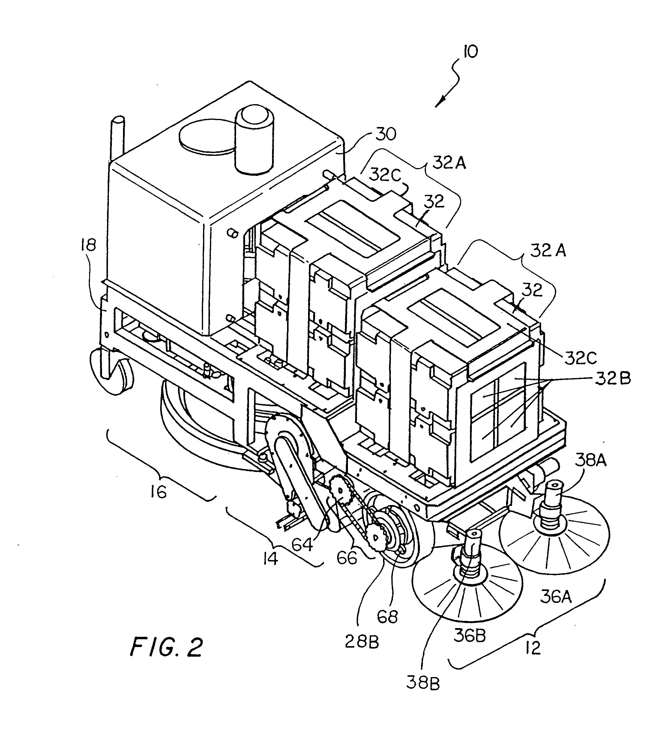
[0077] Referring to FIGS. 1, 2, 3, and 3A, a cleaner 10 typically includes a sweeper assembly 12, a scrubber assembly 14, and a burnisher assembly 16, each of which is mounted on a common frame 18. In one embodiment, cleaner 10 may only include scrubber assembly 14 and burnisher assembly 16. Cleaner 10 also includes a housing 20 which is fastened to frame 18. Cleaner 10 is preferably sized to fit in aisles of typical retail stores such as grocery stores and department stores. Such aisles typically have widths greater than or equal to about 24 inches, and more typically ranging from about 39 to about 72 inches.

[0078] Cleaner 10 further includes a vacuum and cleaning liquid subsystem 30 to which scrubber assembly 14 is connected. Vacuum and liquid subsystem 30 is responsible for depositing a cleaning liquid on a scrubber brush of scrubber assembly 10 and recovering the deposited liquid from the floor. Cleaner 10 also includes batteries 32 which supply power to the various circuits an...


PUM


Abstract

A floor cleaner is provided for cleaning a floor, where the floor cleaner has a front and a rear and includes: a sweeper for sweeping the floor; a scrubber, connected to the sweeper and located in the rear of the sweeper, for wetting and cleaning the floor; and a burnisher, connected to the scrubber and located in the rear of the scrubber, for burnishing the floor.

Description

RELATED APPLICATIONS [0001] This application claims priority of U.S. Provisional Application Ser. No. 60 / 138,179 filed Jun. 8, 1999.FIELD OF THE INVENTION [0002] This invention relates to floor cleaning systems or cleaners for cleaning floors such 110 as waxed floor surfaces including Vinyl Composition Tile (VCT) floors with a glossy polymeric finish such as an Ultra High Speed (UHS) commercial finish. BACKGROUND OF THE INVENTION [0003] Modern resilient and hard flooring materials are often coated with polymer coatings which may be natural or synthetic polymers, sometimes referred to as “floor waxes”. These coating materials can impart various types of finish to the floors. Acrylic polymers are often used on such floors where a transparent, glossy finish is desired. Following application of the coating materials, the floor must be periodically swept, scrubbed and polished to restore the shine worn by foot and other traffic on the floor. For glossy floors, the burnishing and other op...

Claims


Application Information

Patent Timeline
Patent Type & Authority Applications(United States)
IPC IPC(8): A47L11/14A47L11/164A47L11/20A47L11/24A47L11/282A47L11/283A47L11/29A47L11/30A47L11/40
CPCA47L11/14A47L11/24A47L11/282A47L11/30A47L11/4011A47L11/4088A47L11/4038A47L11/4041A47L11/4044A47L11/4052A47L11/4069A47L11/4036A47L11/03
Inventor THOMAS, VICTOR W. SR.KAY, ROBERT K.SHARMA, JAYANTMASS, PHILLIP R.ROBERT, ROSARIOANGLE, COLINSWORD, LEE F.JONES, JOSEPH L.SANDIN, PAUL E.O'BRIEN, JOHN P.WIRZ, BENJAMIN L.SLIPICHEVICH, SELMACHIAPPETTA, MARKCOLTOF, GIDEONCONNORS, ROBERT A.
Owner JOHNSONDIVERSEY INC
Why Eureka
Try Eureka