
Vacuum lumber drying kiln with collapsing cover and method of use

a vacuum chamber and kiln technology, which is applied in the direction of drying machines with progressive movements, lighting and heating apparatus, furnaces, etc., can solve the problems of occupying valuable kiln space, reducing operational efficiency in two ways, and prone to warpage and twisting in the kiln, so as to achieve flexible size and operation, low initial cost

Inactive Publication Date: 2005-02-10
MERSCHAT JOHN R
View PDF8 Cites 13 Cited by
  • Summary
  • Abstract
  • Description
  • Claims
  • Application Information

AI Technical Summary

Benefits of technology

[0013] The lumber drying kiln of the present invention solves the aforementioned problems by providing a vacuum kiln design which is of relatively low initial cost and is flexible in size and mode of operation so as to appeal to a large range of users from the small to the large lumber kiln operator.
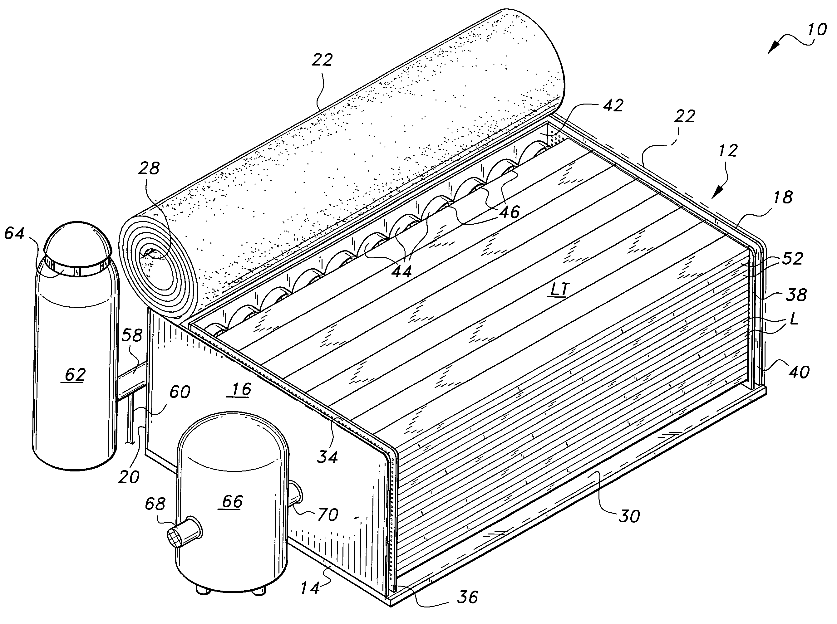
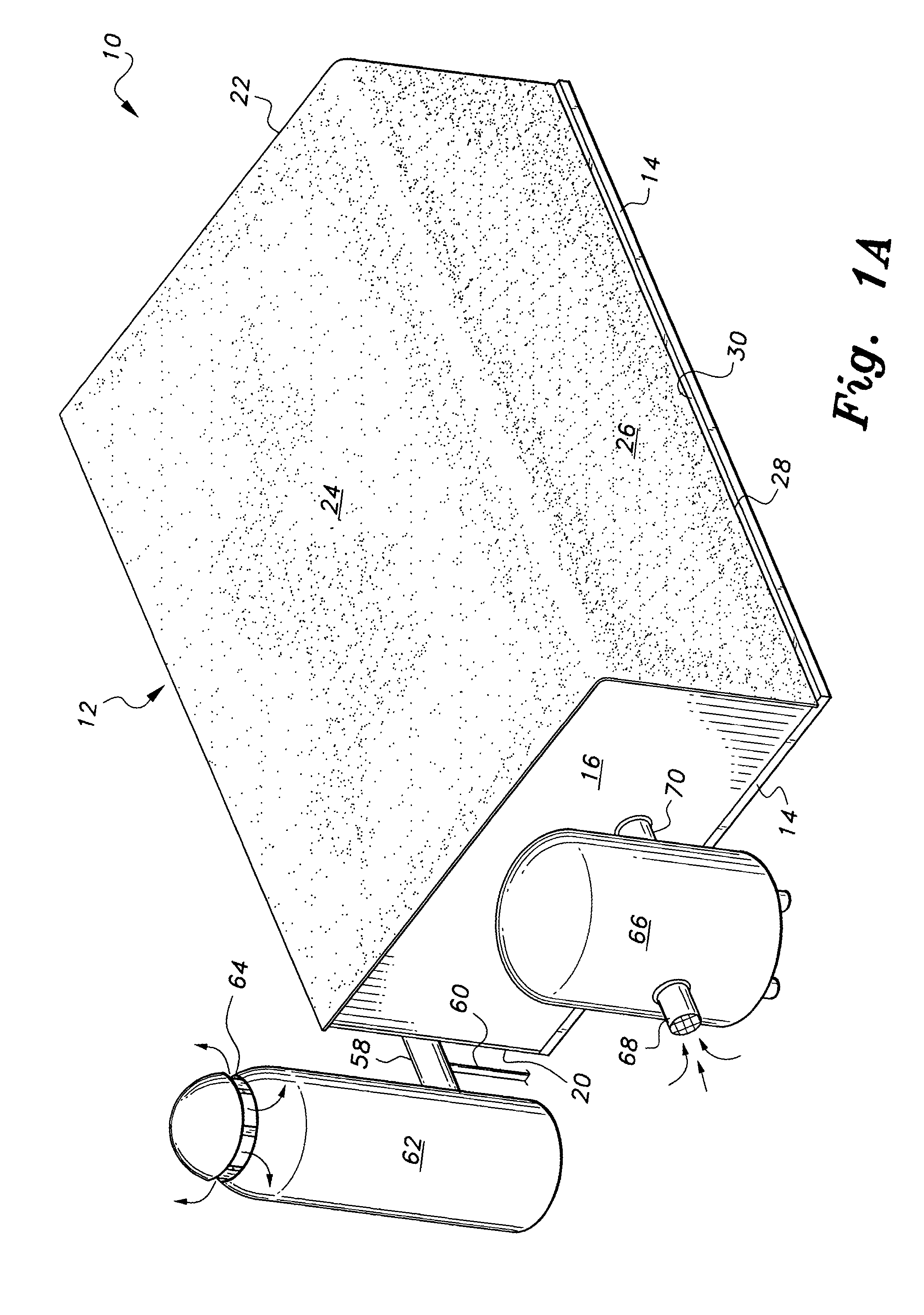
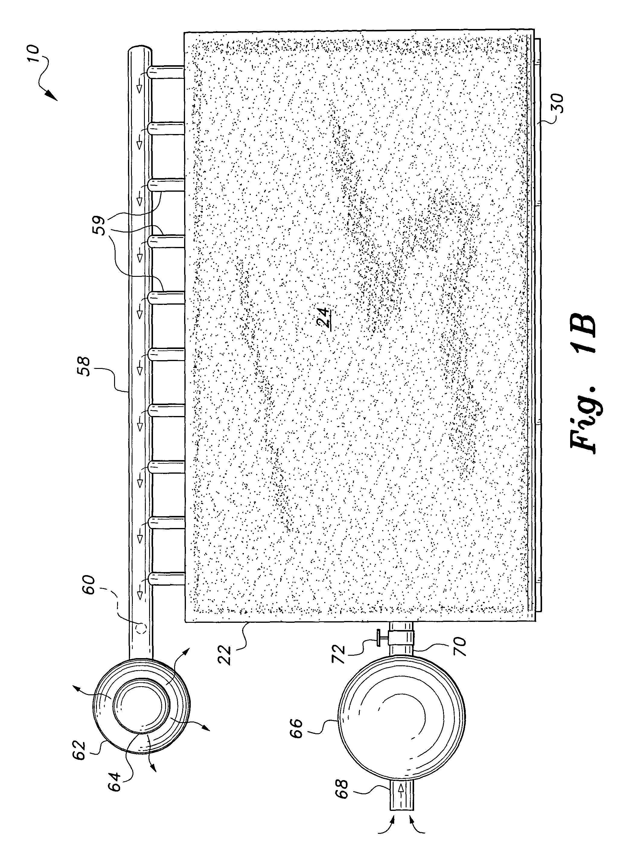
[0014] In the present invention the stack of lumber, itself is employed to support the vacuum chamber using a flexible collapsing bag or cover alone or in combination with walls. The collapsing bag seals against a base, which may be heated or unheated, to maintain the vacuum. In its simplest form a stainless steel platform or base is made to support a stack of lumber. The lumber stack has alternating layers of hot plates or stickers separating layers of lumber. A bag having an open bottom and made of nylon-reinforced rubber or other strong flexible material is placed over the wood and sealed to the stainless steel platform. A vacuum pump is connected with the bag by means of a manifold and operated to remove air from the enclosed lumber stack, the vacuum strengthening the seal between the base and the bottom of the bag. This chamber may be made as small or large as necessary to satisfy any user. This chamber is less expensive to construct and the lumber is flatter and has fewer top layer defects than prior systems.

Problems solved by technology

As lumber dries, it has a tendency to warp and twist in the kiln.
This does help relieve the problem, but reduces operational efficiency in two ways.
First, the large concrete or steel weights take up valuable kiln space that could be used for drying wood.
Second, the weights must be heated to whatever temperature the kiln is running, wasting energy.

Method used


Image

  • Vacuum lumber drying kiln with collapsing cover and method of use
  • Vacuum lumber drying kiln with collapsing cover and method of use
  • Vacuum lumber drying kiln with collapsing cover and method of use

Examples


Embodiment Construction

[0056] The present invention is a wood drying kiln having a flexible cover allowing the stack of lumber, itself, to be employed to support the vacuum chamber using a flexible collapsing bag or cover alone or in combination with walls. The collapsing bag seals against a base, which may be heated or unheated to maintain the vacuum. In its simplest form a stainless steel platform or base is made to support a stack of lumber. The lumber stack has alternating layers of hot plates or stickers separating layers of lumber. A bag having an open bottom and made of nylon-reinforced rubber or other strong flexible material is placed over the wood and sealed to the stainless steel platform. A vacuum pump is connected with the bag by means of a manifold and operated to remove air from the enclosed lumber stack, the vacuum strengthening the seal between the base and the bottom of the bag.

[0057] Referring to FIGS. 1A-1I, there is shown one embodiment of the present invention wherein stickers are u...


PUM


Abstract

A lumber drying kiln employs outside air pressure uses a flexible collapsing bag or cover alone or in combination with walls. The collapsing bag seals against a base to maintain the vacuum. The air pressure against the flexible top keeps the lumber layers from warping or cupping during drying. The lumber stack has alternating layers of hot plates or stickers separating layers of lumber. A bag having an open bottom and made of nylon-reinforced rubber or other strong flexible material is placed over the wood and sealed to the stainless steel platform. A vacuum pump is connected with the bag by means of a manifold and operated to remove air from the enclosed lumber stack, the vacuum strengthening the seal between the base and the bottom of the bag. This chamber design is easily scaled up or down to provide a desired drying capacity.

Description

BACKGROUND OF THE INVENTION [0001] 1. Field of the Invention [0002] The present invention relates to kilns for drying lumber. More particularly, the present invention relates to a vacuum chamber kiln. [0003] 2. Description of the Related Art [0004] The use of lumber drying kilns is widespread for preparing lumber for use in building furniture, flooring, and other applications where warping of lumber during and after incorporation in the product or structure is not acceptable. In the past, lumber was air dried or cured in stacks, either outdoors in the weather, or indoors, taking lengthy time to reach the required dried or cured conditions. Drying kilns have speeded the drying or curing of wood to a relatively short time and produce more consistent quality lumber. [0005] There are differing ways to kiln dry lumber. Steaming and dehumidification are examples. The drawbacks to these are the time and energy it takes to achieve the desired final moisture content in the wood. It typically...

Claims


Application Information

Patent Timeline
Patent Type & Authority Applications(United States)
IPC IPC(8): F26B5/04F26B7/00F26B9/00F26B25/18
CPCF26B5/045F26B7/00F26B2210/16F26B25/185F26B9/006
Inventor MERSCHAT, JOHN R.
Owner MERSCHAT JOHN R
Learn More