Solar electricity generator

a solar power generator and solar energy technology, applied in the direction of machines/engines, heat collector mounting/support, light and heating equipment, etc., can solve the problems of high cost due to metal mass, large east-west separation of concentrator modules, and additional cost factors due to high maintenance labor involved, etc., to achieve optimal cell operation

Inactive Publication Date: 2005-02-10
PYRON SOLAR III +1
View PDF14 Cites 22 Cited by
  • Summary
  • Abstract
  • Description
  • Claims
  • Application Information

AI Technical Summary

Benefits of technology

[0018] d) Short focal-length concentrating lenses and kaleidoscopic mixing rods,

Problems solved by technology

Their high cost and considerable height lead to wide east-west separation of concentrator modules.
Their high cost is due to the masses of metal required for the wind-loads generated by the height, while the height, ironically enough, is required in order to extend the number of hours per day that each module operates without being shadowed by its southern neighbors.
Additional cost factors accrue from the high maintenance labor involved in solar thermal electrical generation.
Large-scale photovoltaic plants have only recently become economically viable due to the steadily decreasing photovoltaic-cell costs and steadily increasing cell efficiency.
But without concentration, covering huge tracts of land with banks of

Method used


Image

  • Solar electricity generator
  • Solar electricity generator
  • Solar electricity generator

Examples


Embodiment Construction

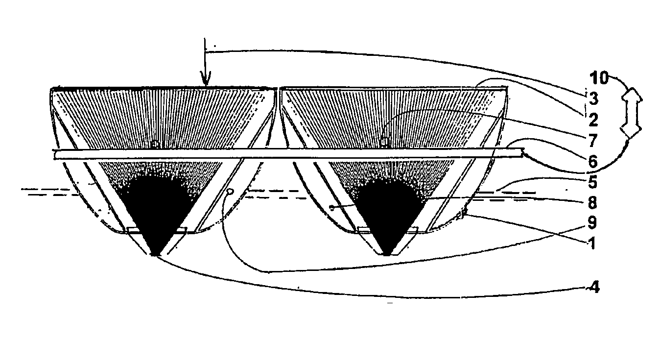
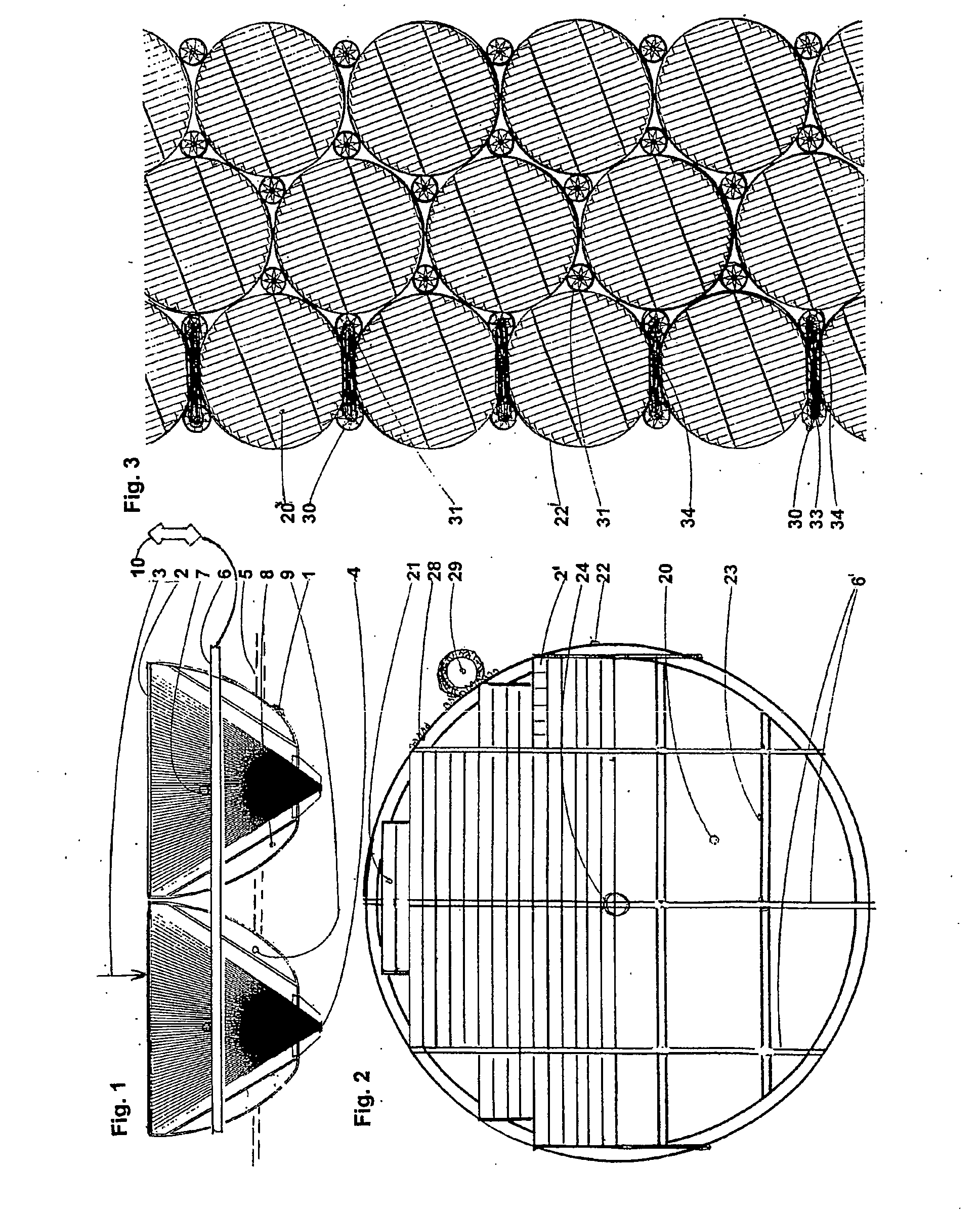
[0038]FIG. 1 shows in schematic presentation a vertical section through concentrators positioned in troughs 1, covered by lenses 2 which concentrate parallel monochromatic rays 3 at focal spot 4. The troughs are supported on water body 5. The troughs are kept at a distance of only a few millimeters from each other by traverses 6. For tracking in solar elevation, the troughs can pivot around the horizontal geometric axis 7. The pivoting is controlled by sun-tracking sensors and is based on pneumatically driven balancing torques. By pumping water from ballast compartment 8 into ballast compartment 9, the two of which pneumatically inter-communicate via tube-shaped traverse 6, a buoyancy-torque makes each trough pivot upward to keep lens 2 aimed directly at the climbing sun, until it has reached its highest position at noon. Thereafter blower 10 creates positive pressure in ballast compartment 9 through traverse 6, so that water flows back from ballast compartment 9 into ballast compar...


PUM


Abstract

Disclosed is a floating altazimuth-tracking array of point-pocus lenses that concentrate direct sunlight on the upper ends of optical-homogenizer rods bonded to high-efficiency multi-junction photnvoltaic cells. The cells are on heat sinks in altitude-tracking linear troughs holding multiple lens-rod-cell assemblies. Swiveling on horizontal axes, the troughs have their heat sinks always submerged in the water of a circular pond. Only knee-high al-together, the troughs and their floating frame rotate in the shallow pond for azimuth tracking. Closely packed floating platforms comprise solar electric farms with maximal land utilization.

Description

FIELD OF THE INVENTION [0001] The invention refers to photovoltaic solar power plants of large size. BACKGROUND OF THE INVENTION [0002] The invention refers to devices for the direct conversion of solar energy into electricity, in contrast to indirect conversion involving elevated-temperature intermediary processes producing mechanical torque that is applied to rotary electrical generators. Large solar electricity generators are known to be currently operating in California. All of the largest first concentrate sunlight into high-temperature heat and thereafter, with methods known from combustion-heated power-stations, partially into electricity, the rest waste heat. All currently operating solar power plants with utility-significant electrical-output cover huge tracts because their areal yield is below 3%. Their high cost and considerable height lead to wide east-west separation of concentrator modules. Their high cost is due to the masses of metal required for the wind-loads gener...

Claims


Application Information

Patent Timeline
IPC IPC(8): H01L31/042F03G6/00F24J2/52H01L31/0232H01L31/052
CPCF24J2/5267F24J2002/5292H01L31/0232Y02E10/52Y02E10/46Y02E10/47H01L31/052H02S20/32H01L31/0543H02S40/42F24S2025/02F24S20/70F24S30/42
Inventor LAINGPARKYN JR, WILLIAM ARTHURLAING, INGE
Owner PYRON SOLAR III
Why Eureka
Try Eureka