
Burner for a gas-turbine combustion chamber

a combustion chamber and burner technology, which is applied in the direction of machines/engines, mechanical equipment, lighting and heating apparatus, etc., can solve the problems of reduced temperature of air-fuel mixture, high number of parts, and inability to ensure the stability of the flame, so as to achieve the effect of ensuring stability

Inactive Publication Date: 2005-02-10
ROLLS ROYCE DEUT LTD & CO KG
View PDF20 Cites 34 Cited by
  • Summary
  • Abstract
  • Description
  • Claims
  • Application Information

AI Technical Summary

Benefits of technology

[0009] The present invention, in a broad aspect, provides a burner of the type mentioned above which ensures stability of the flame in the combustion chamber throughout the operating range of a gas-turbine engine and safe operation of the gas turbine at any time.
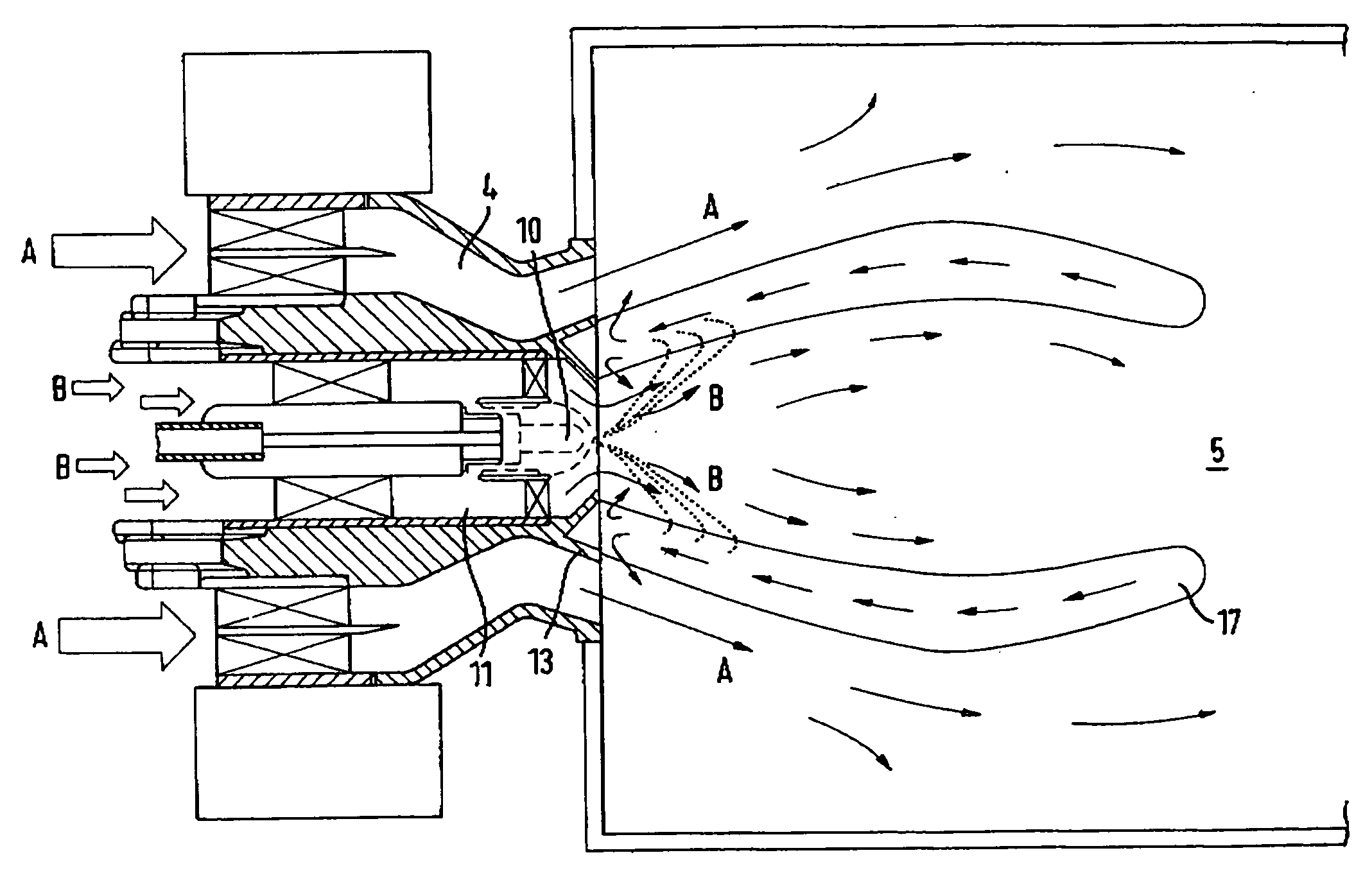
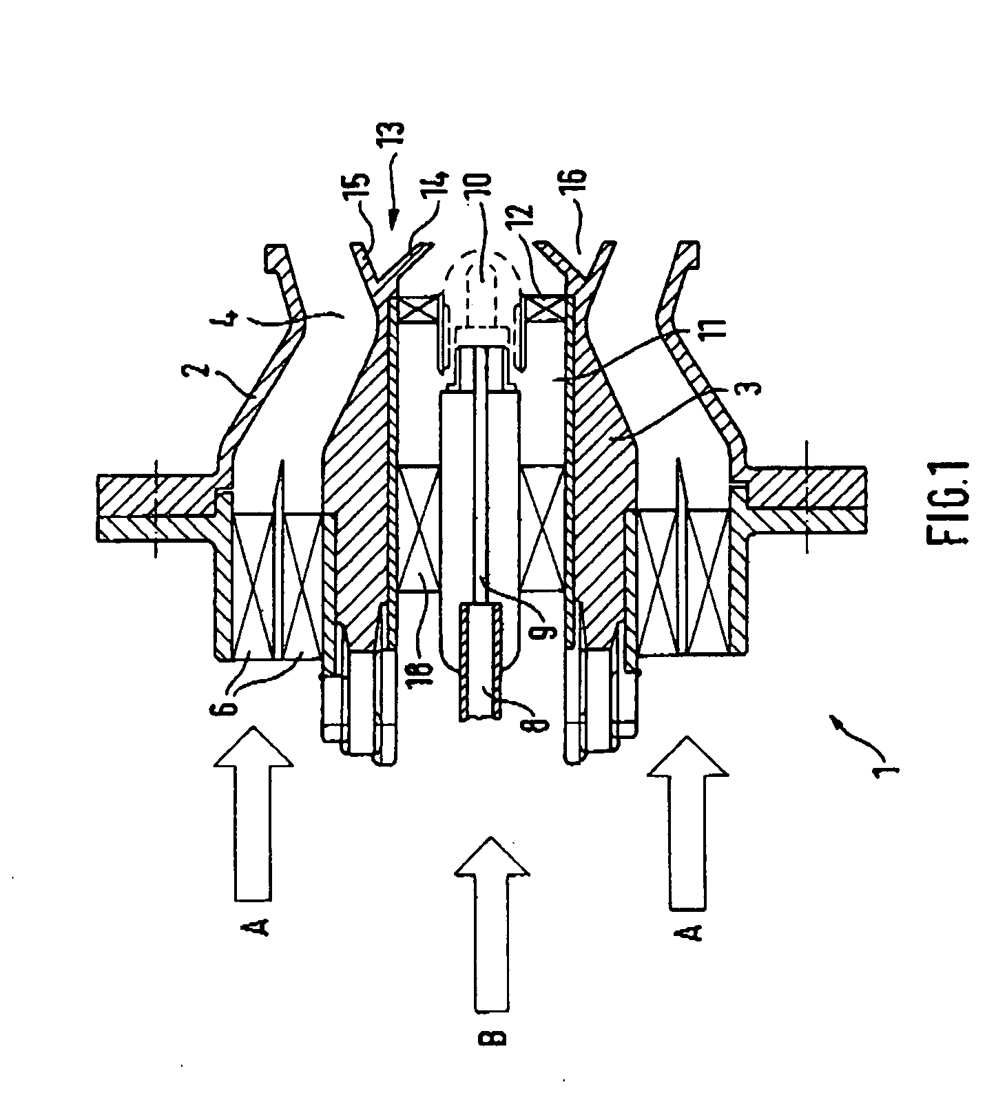
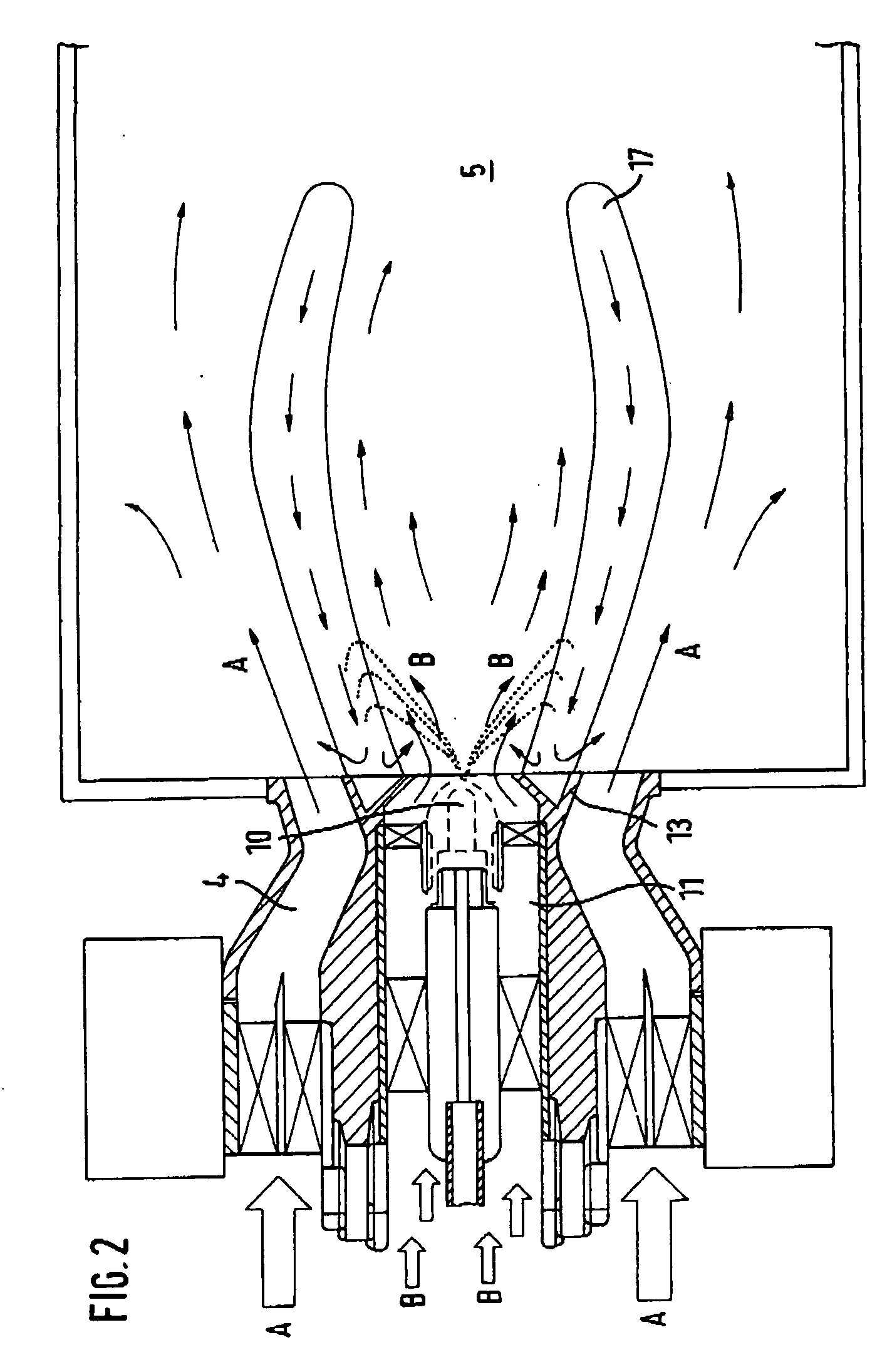
[0011] The idea underlying the present invention with respect to a lean premix burner with a weak air-fuel mixture supplied via a main air annulus and a stabilizing burner integrated centrally into the lean premix burner with a core air annulus surrounded by the main air annulus and with an atomizer nozzle for fuel arranged at the exit port of the core air annulus is to provide, in the adjacent issuing areas of the concentric annuli, a flame stabilization ring which is highly heated by the combustion process and whose air deflector flanks direct the main air-fuel mixture outwards and the core airflow inwards. The gas flow produced by the hot flame stabilization ring effects the formation of a hot, approximately hollow-cylindrical to barrel-shaped, steady recirculation zone or hot-gas zone which originates at the flame stabilization ring and, together with the stabilization ring, acts as an igniting element and in which the fuel discharged from the stabilizing burner is caught and completely burnt. The flame stabilization ring in accordance with the present invention ensures that a stable, non-extinguishing flame is provided in any operating state of a gas turbine equipped with a lean premix burner and integrated stabilizing burner, even if external conditions lead to a decrease of the air temperature, thus ensuring the operational reliability of the gas-turbine engine.
[0012] In accordance with a further, feature of the present invention, the flame stabilization ring is an annular ring having a generally triangular cross-section incorporating a fillet which is enclosed by two legs and is open to the combustion chamber. The legs form, on the burner-facing side, the deflector flanks for the inwardly flowing core air or the outwardly flowing main air-fuel mixture, respectively. Simultaneously, the fillet or the legs, respectively, of the flame stabilization ring provide the cooling necessary to prevent the ring from overheating. Cooling is effected at the air deflector flanks of the relatively thin-walled legs of the flame stabilization ring by the core or main air supplied.

Problems solved by technology

The use of such burners is, however, disadvantageous in that the stability of the flame is not ensured.
On gas-turbine engines for aircraft, this problem exists, in particular, at low ambient temperatures, in hail or rain showers or under similar, adverse meteorological conditions resulting in a reduced temperature of the air-fuel mixture.
Besides complexity, high number of parts, high manufacturing costs and high weight, cooling of the large surfaces involves considerable investment.
Other types of lean premix burners using stabilizing means in which the ignition burner is centrally integrated do not have the design disadvantages described above, but are not considered successful since they fail to satisfy both a lean overall ratio of the air-fuel mixture required and stable operation of the centrally arranged stabilizing burner.
Besides this, transient operating points must be flyable: Particularly unfavorable here is the transition from part load in cruise to flight idle in descent.
Further, maneuvers are encountered in which engine thrust must be reduced very rapidly, with the decrease in fuel flow leading to extremely weak air-fuel ratios.
In addition, all these unfavorable operating points must, as already mentioned, be flyable under extreme meteorological conditions, such as hailstorms or tropical rain.
A flame formation which is stable throughout the range of operating conditions can, however, not be achieved With this burner design.

Method used


Image

  • Burner for a gas-turbine combustion chamber
  • Burner for a gas-turbine combustion chamber
  • Burner for a gas-turbine combustion chamber

Examples


Embodiment Construction

[0017] The burner 1 has a casing 2 and a central body 3 between which a main air annulus 4 for a main or lean premix burner associated with a combustion chamber 5 of an (aircraft) gas turbine is formed. The main air annulus 4 of the lean premix burner, through which flow approximately 90 percent of the total combustion air, contains main air swirlers 6 which impart a rotational movement to the main air flow arrow A. Liquid fuel is injected into the swirling main air flow which mixes with, and partly vaporizes in, this hot air flow. The—lean-fuel-air mixture supplied to the combustion chamber 5 has a high air content and, accordingly, burns in the combustion chamber 5 with low combustion temperature, as a result of which nitrogen oxide emissions and air pollution are extremely low.

[0018] While low pollutant emission is obtained with low combustion temperatures, the reduced air entry temperature associated with it may lead to flame instabilities or flame blow out, in particular, unde...


PUM


Abstract

On a burner for a gas-turbine combustion chamber which comprises a lean premix burner with centrally integrated stabilizing burner, a core air annulus (11) accommodating the atomizer nozzle (10) of the stabilizing burner is concentrically surrounded by a main air annulus (4) supplying the weak air-fuel mixture. In the adjacent issuing areas of the main air annulus and the core air annulus, a flame stabilization ring (13), which is heated by the combustion gases and whose cross-sectional surface increases in area toward the combustion chamber (5), is provided to produce an approximately hollow-cylindrical hot-gas recirculation zone (17) originating at the flame stabilization ring which ensures a stable flame formation throughout the range of operating conditions of the gas turbine.

Description

[0001] This application claims priority to German Patent Application DE10326720.4 filed Jun. 6, 2003, the entirety of which is incorporated by reference herein. BACKGROUND OF THE INVENTION [0002] This invention relates to a burner for a gas-turbine combustion chamber, in particular for an aircraft gas turbine, which comprises a lean premix burner with centrally integrated stabilizing burner. [0003] Lean premix burners for gas-turbine engines and for gas turbines in other applications whose combustion chambers burn a fuel-air mixture with high content of air at low combustion temperature and correspondingly reduced nitrogen oxide formation are generally known. The use of such burners is, however, disadvantageous in that the stability of the flame is not ensured. In other words, the air-fuel mixture supplied to the combustion chamber will not burn or be ignited continuously as the combustion temperature falls, as a result of which the flame will fluctuate or may even go out. On gas-tu...

Claims


Application Information

Patent Timeline
IPC IPC(8): F23R3/18F23R3/28F23R3/34
CPCF23D2209/20F23D2900/00008F23R3/343F23R3/18F23R3/286F23D2900/00018
Inventor VON DER BANK, RALF SEBASTIAN
Owner ROLLS ROYCE DEUT LTD & CO KG
Learn More