Vacuum cleaner

a vacuum cleaner and vacuum technology, applied in the field of vacuum cleaners, can solve the problems of not providing much of the pressure drop and achieve the effects of high particle removal, and substantial resistance to the flow

Inactive Publication Date: 2005-02-10
POLAR LIGHT
View PDF97 Cites 47 Cited by
  • Summary
  • Abstract
  • Description
  • Claims
  • Application Information

AI Technical Summary

Benefits of technology

[0014] In order to achieve high levels of particle removal, cyclonic vacuum cleaners which are currently on the market incorporate a HEPA™ filter. Such filters are effective in removing small particulate matter from the air stream so that the air which exits the vacuum cleaner is essentially for refiltered. One disadvantage of such HEPA™ filters is that they provide substantial resistance to the flow of air there through. By removing the H

Problems solved by technology

One disadvantage of such HEPA™ filters is that they provide substantial resistance to the flow of air there through.
Electrostatic filters generally p

Method used


Image

  • Vacuum cleaner
  • Vacuum cleaner
  • Vacuum cleaner

Examples


Embodiment Construction

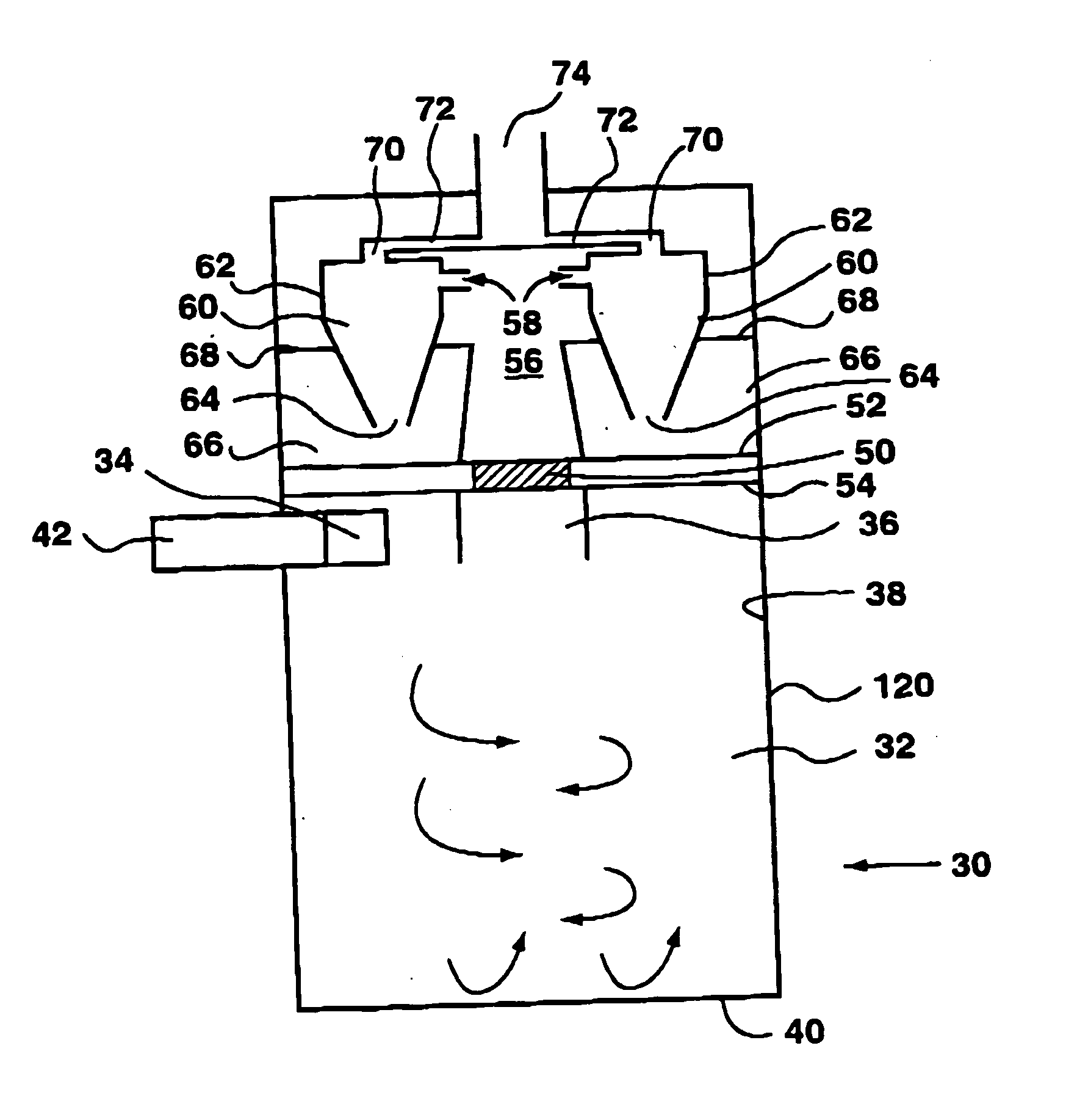
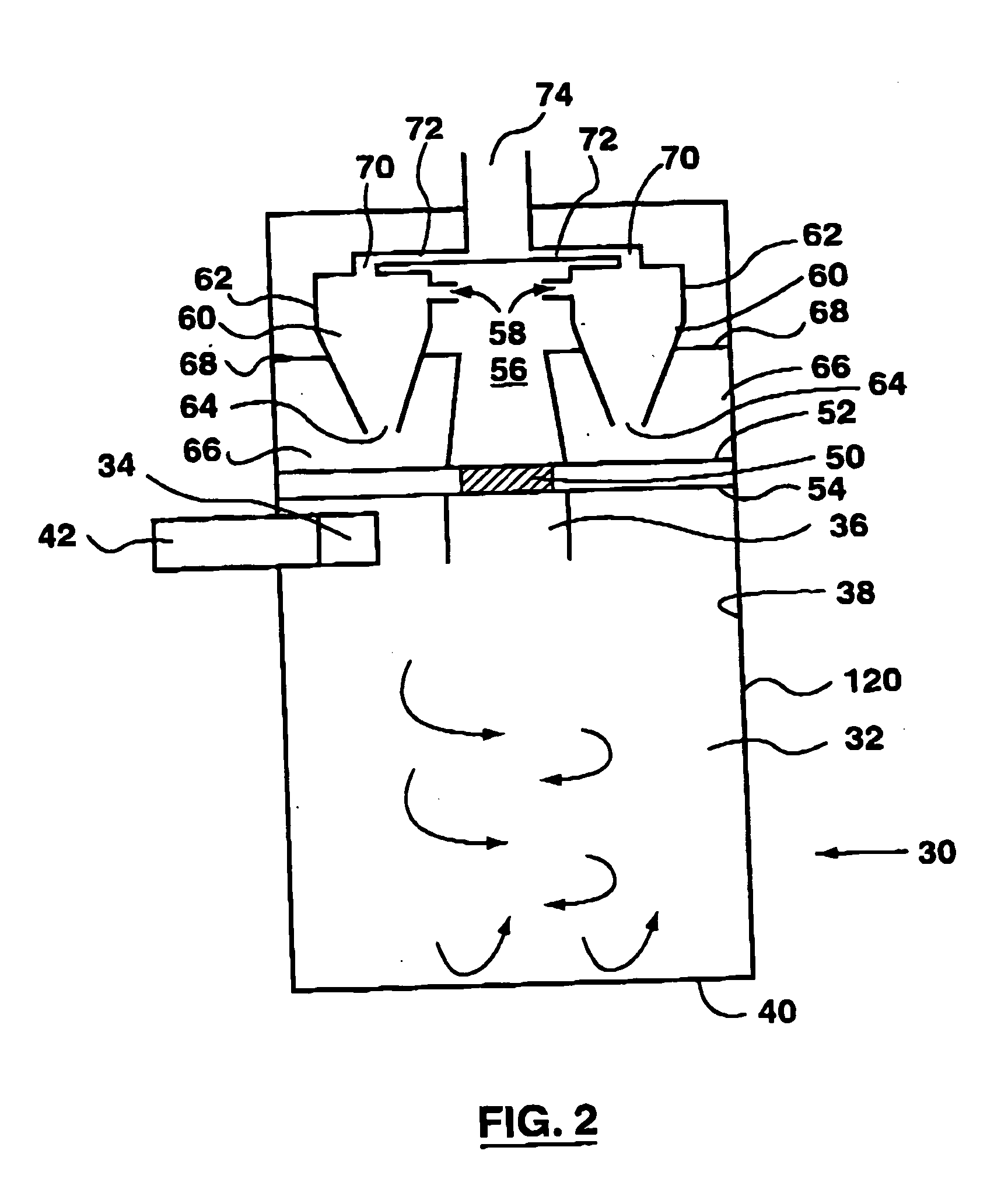
[0071] The filter assembly of the instant invention may be used in conjunction with any vacuum cleaner. For example, the filter assembly may be used for an upright vacuum cleaner, a canister vacuum cleaner or a central vacuum cleaner or the like. The dirty air stream which is processed using the filter assembly described herein may be collected by, for example, a wand or rotating brush positioned in the head of a vacuum cleaner as is known in the art. Such dirty air streams typically comprise dirt of varying particle sizes entrained in an air stream. It will be appreciated that the invention may also be used with a wet / dry vacuum cleaner.

[0072] The filter assembly may be used in conjunction with any design known in the art. For example, as shown in FIGS. 2 and 3, the cyclone may be a cylindrical cyclone having a dirty air feed conduit which is positioned exterior to cyclone bin 120. Alternately, as shown in FIGS. 4 and 5, the cyclone may be a cylindrical cyclone having a dirty air ...


PUM


Abstract

A method for filtering a dirty air stream in a vacuum cleaner to obtain a clean air stream comprises subjecting the dirty air stream to a first cyclonic separation stage to obtain a partially cleaned air stream and subjecting the partially cleaned air stream to an electronic filtration stage and optionally a second cyclonic separation stage to obtain the clean air stream. The electronic filtration stage is optionally removable with a cyclonic cleaning stage from the vacuum cleaner. The electronic filtration stage is optionally an electrostatic precipitator which utilizes air flow through the vacuum cleaner to generate the voltage used by the electrostatic precipitator.

Description

[0001] This applicatin is a continuation of U.S. application Ser. No. 10 / 043,337, now allowed, which is a continuation of U.S. patent application Ser. No. 09 / 478,891 filed on Jan. 7, 2000 which has issued as U.S. Pat. No. 6,383,266 which is a continuation-in-part of U.S. patent application Ser. No. 09 / 227,712 filed on Jan. 8, 1999 which has issued as U.S. Pat. No. 6,238,451.FIELD OF THE INVENTION [0002] This invention relates to vacuum cleaners which have a cyclonic separation apparatus. In another aspect, the invention relates to an electrostatic precipitator. BACKGROUND OF THE INVENTION [0003] Cyclone separators, which are sometimes referred to merely as cyclones, are devices that utilize centrifugal forces and low pressure caused by spinning motion to separate materials of differing density, size and shape. FIG. 1 illustrates the operating principles in a typical cyclone separator (designated by reference numeral 10 in FIG. 1). The following is a description of the operating prin...

Claims


Application Information

Patent Timeline
IPC IPC(8): A47L9/12A47L9/16B01D45/16B01D50/00B04C5/24
CPCA47L9/122A47L9/1625A47L9/1641A47L9/1666Y10S55/03B01D45/16B01D50/00B04C5/24B04C2009/002A47L9/1691
Inventor CONRAD, WAYNE ERNESTGERHARD CONRAD, HELMUT
Owner POLAR LIGHT
Why Eureka
Try Eureka