Nasal ventilation interface

a nasal tube and interface technology, applied in the field of nasal tube systems, can solve the problems of inability to ensure ventilation in many patients, inability to provide positive seal between the nasal insert tube and the nostrils, masks and headgear tend to be rather constraining and uncomfortable, etc., to achieve minimal or no leakage of gas from the nostrils, improve patient comfort, and increase gas delivery efficiency

Inactive Publication Date: 2005-02-10
SALTER LABS LLC
View PDF81 Cites 36 Cited by
  • Summary
  • Abstract
  • Description
  • Claims
  • Application Information

AI Technical Summary

Benefits of technology

[0017] It is another object of the present invention to provide a nasal ventilation interface having improved patient comfort for use over extended periods.
[0018] It is a fur

Problems solved by technology

Conventional nasal tube systems do not provide a positive seal between the nasal insert tubes and the nostrils.
Such systems frequently suffer from air leaking out around the mask, creating an inability to assure ventilation in many patients.
The mask, headgear, and/or straps thereby exert more than a minor pressure on the patient's face and/or head, resulting in such masks and headgear tending to be rather constraining and uncomfortable.
Additionally, most systems are usually very position dependent, whereby if the mask is moved slightly with respect to the facial contour or with respect to the nose, air leakage occurs.
With such systems, the mask can become uncomfortable when not in position, thus requiring the patient to remain rather still in order to alleviate the discomfort and to maintain oxygen inspiration.
As a result many patients lose interest in using the nasal mask.
Such ventilation systems with exhale valves are typically bulky and heavy.
Such systems are low pressure systems for providing oxygen enrichment to the ambient air that the patient breathes, are not

Method used


Image

  • Nasal ventilation interface
  • Nasal ventilation interface
  • Nasal ventilation interface

Examples


Embodiment Construction

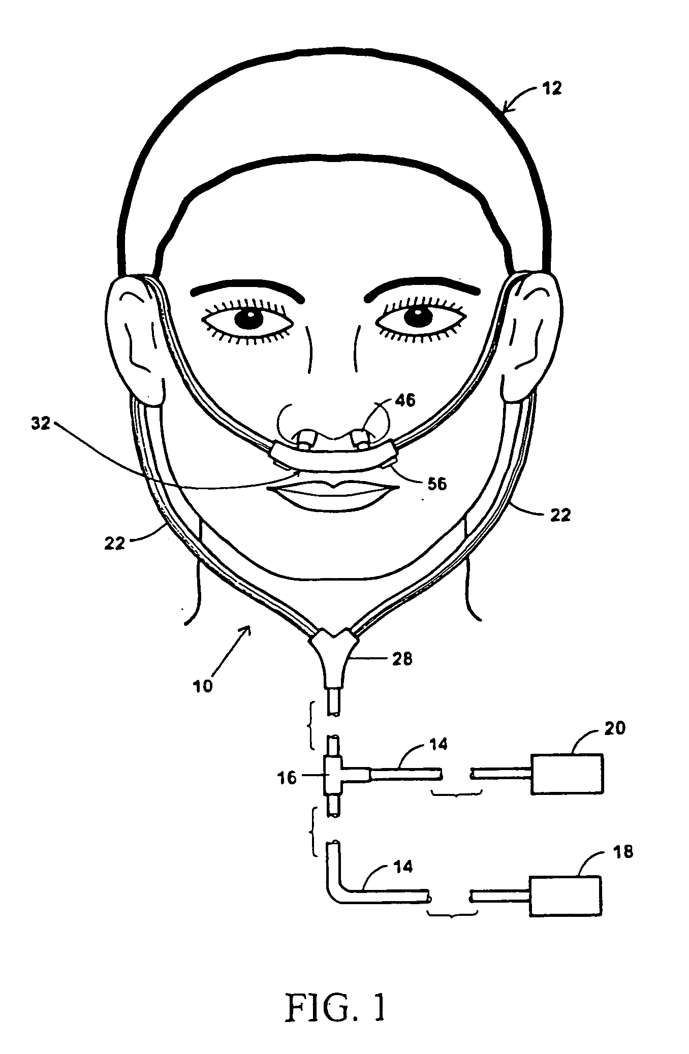
[0042] Referring now to FIG. 1, there is illustrated a first embodiment 10 of the present nasal interface invention as typically worn by a patient 12. The interface 10 may be connected by feed tubing 14 and a feed valve 16 to a mechanical ventilator 18 and a gas supply 20. The feed tubing 14 may be a thin flexible tube made of an inert material such as polyurethane, silicone, or another material known in the art. It will be noted that all components of the interface 10 may be made of medical grade biocompatible materials.

[0043] The mechanical ventilator 18 forces a gas such as air through the tubing 14. The mechanical ventilator 18 may be provided by a continuous positive airway pressure (CPAP) machine for constant air pressure delivered through the interface 10 to the patient 12. Alternatively, the mechanical ventilator 18 may be provided by a bilateral positive airway pressure (BIPAP) machine for intermittent air pressure delivered through the interface 10 to the patient 12, wher...


PUM


Abstract

A nasal ventilation interface comprising a hollow body having at least one and preferably two nasal apertures, and at least one and preferably two inhale apertures, and at least one and preferably two nasal insert tubes each associated with one of the nasal apertures and having an annular sleeve that forms a seal with a nostril of the patient. The hollow body has at least one and preferably two exhale apertures and at least one valve assembly associated with the exhale apertures that are capable of preventing air from passing through the exhale aperture upon the patient inhaling and allowing air to pass through the exhale aperture upon exhaling. The hollow body may also have at least one and preferably two filters for retaining heat and moisture from the exhale air and transferring the retained heat and moisture into the inhale air.

Description

CROSS-REFERENCE TO RELATED APPLICATIONS [0001] This application is a continuation of U.S. patent application Ser. No. 10 / 044,925, currently pending, which is a continuation-in-part of U.S. patent application Ser. No. 09 / 524,371, issued as U.S. Pat. No. 6,478,026, on Nov. 12, 2002, the disclosures of which are incorporated by reference herein in their entirety.FIELD OF THE INVENTION [0002] The present invention relates generally to nasal ventilation systems, and more particularly, to a valved nasal ventilation interface for supporting respiration. BRIEF DESCRIPTION OF THE PRIOR ART [0003] Nasal ventilators generally consist of tubes and other means for delivering gases adapted for use with the nasal or oral passage of a patient. Typically, a nasal ventilation system comprises a gas source and a mechanical ventilator such as a continuous positive airway pressure system (CPAP), bi-level positive airway pressure system (BIPAP), or intermittent (non-continuous) positive pressure (IPPB). ...

Claims


Application Information

Patent Timeline
IPC IPC(8): A61M16/06A61M16/10
CPCA61M16/0666A61M16/208A61M16/1045A61M16/0816A61M16/1055A61M16/0833A61M16/101A61M16/106
Inventor WOOD, THOMAS J.
Owner SALTER LABS LLC
Why Eureka
Try Eureka