Ultrasound horn

Inactive Publication Date: 2005-02-10
TETRA LAVAL HLDG & FINANCE SA
View PDF10 Cites 3 Cited by
  • Summary
  • Abstract
  • Description
  • Claims
  • Application Information

AI Technical Summary

Benefits of technology

[0013] By forming the rounding off of the recess in this manner with different radii, it is possible to even out the tension distribution along the rounding off and moreover reduce the maximum tension. It is interesting to note that if the rounding off is designed with more than one radius, one of the radii will automatically be less than the nominal radius which could have been employed if only one radius was used for the rounding off. Thus, the construction according to the present invention entails that, directly contrary to conventional design and construction rules, a radius is made smaller with a view to reducing the tensions at the rounding off. Despite implementing this different design, it has proved that the tension level falls and is evened out thanks to the rounding off being composed of several different radii.
[0015] Advantageously, the recess at the rounding off is of a width which is less than the first radius of curvature. By such means, an even transition will be obtained between the substantially straight section of the recess to the beginning of the rounding off, which further contributes in reducing and evening out the tension level at the rounding off. For the same reason, the recess is, preferably adjacent the rounding off, of a width which is less than the third radius of curvature.
[0016] According to one preferred embodiment, the second radius of curvature is less than the first radius of curvature. As a result of the smaller radius, it is possible to obtain even transitions between the radii and still obtain the entire sweeping angle of 180° so that the rounding off connects to both sides of the recess. As was mentioned above, this smaller radius surprisingly contributes in evening out and reducing the tension level at the rounding off. For a corresponding reason, the second radius of curvature is smaller than the third radius of curvature.
[0017] According to one preferred embodiment, the second radius of curvature is less than the width of the recess adjacent the rounding off. As was mentioned above, the smaller radius makes it possible to obtain even transitions between the radii and nevertheless retain the entire sweeping angle of 180° so that the rounding off connects to both sides of the recess. As was mentioned above, this smaller radius surprisingly contributes in evening out and reducing the tension level at the rounding off. For the corresponding reason, the second radius of curvature is preferably also smaller than the width of the recess adjacent the rounding off.
[0021] The above-outlined problem has been solved for this ultrasound horn in that it has been given the characterising features that the transfer section has at least a first portion with a first radius of curvature and a second portion with a second radius of curvature, and that, of said portions, the first portion is located more proximal the fixing section and the radius of curvature of the first portion is less than the radius of curvature of the second portion. As was described in detail above, the curving of the transfer section composed of a plurality of radii contributes in evening out and reducing the tension level, which implies that it is possible to reduce the amount of material in the transfer section. This is desirable not only for reasons of weight and cost, but also for functional reasons. It is possible to imagine an ultrasound horn of this type as being a large mass (the fixing section), a spring (the transfer section) and a small mass (the sealing section) where a slight oscillation applied on the large mass will be transferred by the spring to the smaller mass which will oscillate with substantially the same amount of movement, which implies that it will oscillate with considerably greater amplitude than the large mass. A slim transfer section refines this functional model.
[0023] The above-outlined problem has been solved for this ultrasound horn in that it has been given the characterising features that the recesses have at least a first portion with a first radius of curvature and a second portion with a second radius of curvature, and that of said portions, the first portion is located more proximal the fixing section and the radius of curvature of the first portion is larger than the radius of curvature of the second portion. As was mentioned above, the recess composed of a plurality of radii contributes in evening out and reducing the tension level in the proximity of the recess.

Problems solved by technology

Despite implementing this different design, it has proved that the tension level falls and is evened out thanks to the rounding off being composed of several different radii.

Method used


Image

  • Ultrasound horn
  • Ultrasound horn
  • Ultrasound horn

Examples


Embodiment Construction

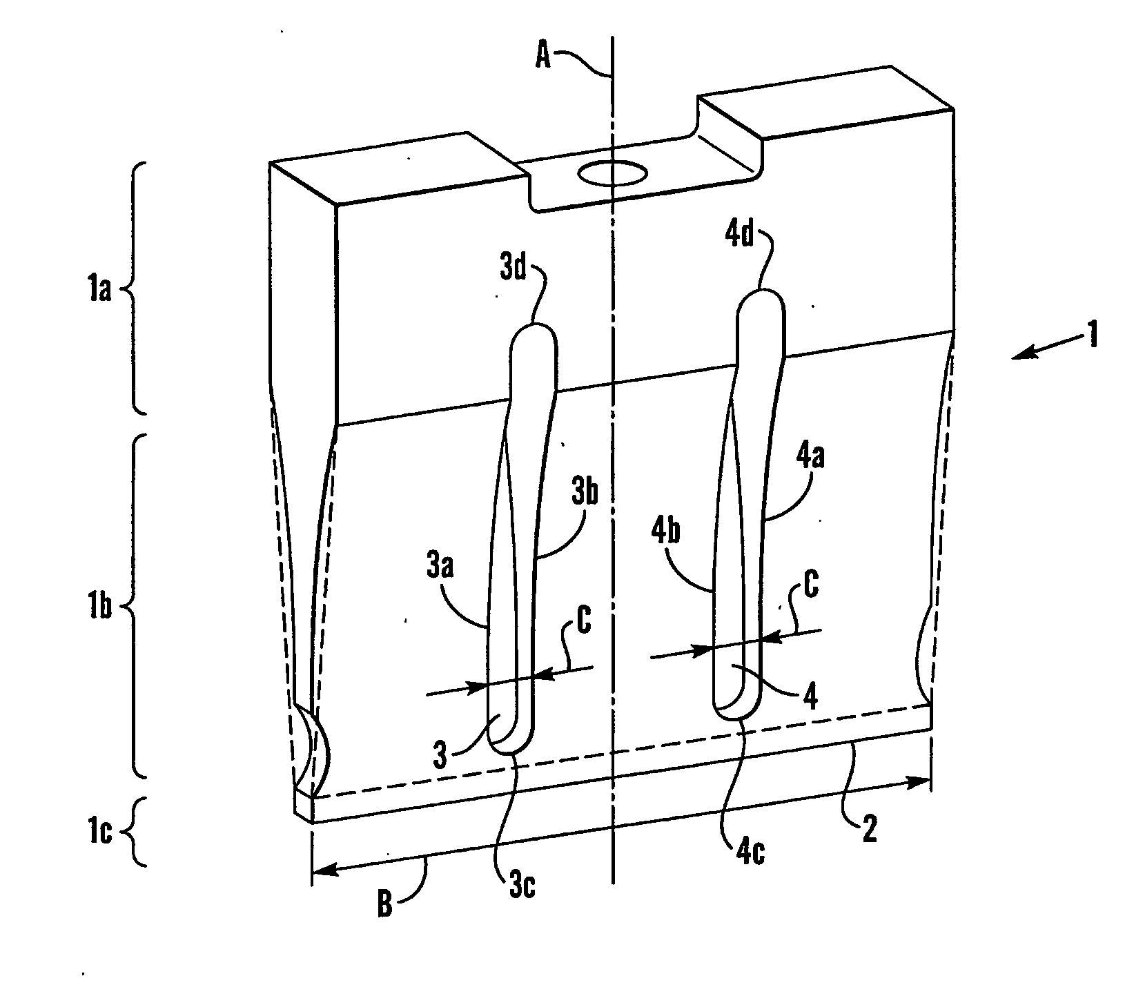
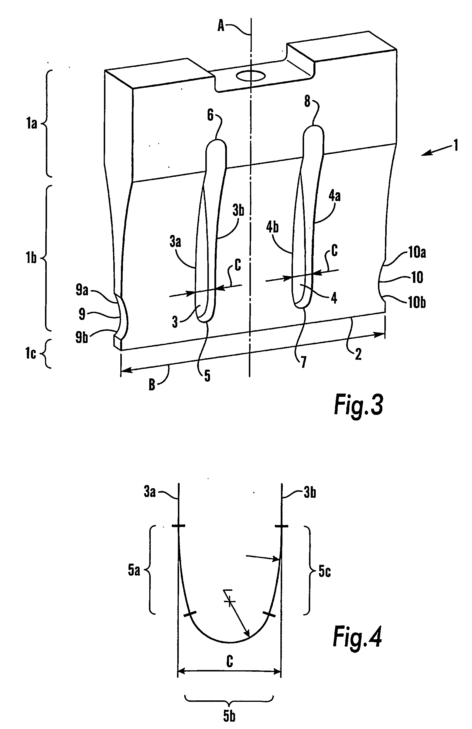
[0031] In the figures, the same reference numerals are employed for those parts which are common to the prior art construction and for those different embodiments according to the invention. FIG. 3 shows an ultrasound horn which is intended to be connected to a drive unit and possibly a booster in the conventional manner (not shown).

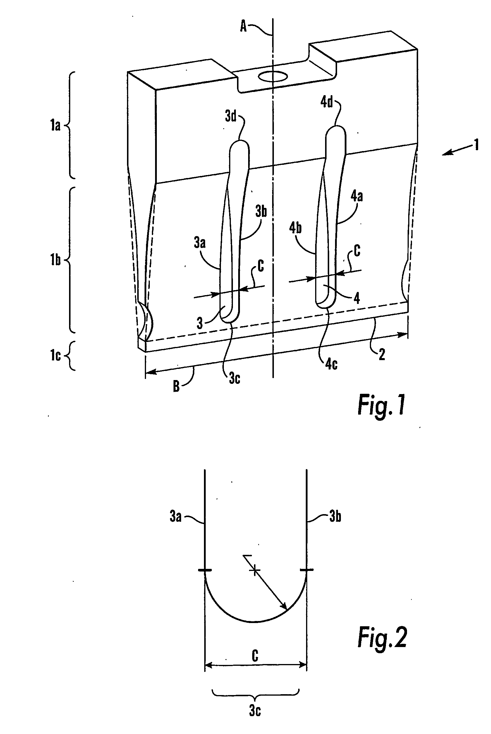
[0032] The ultrasound horn 1 is substantially constructed from a fixing section 1a, a transfer section 1b and a sealing section 1c which extend along a straight line. The ultrasound horn 1 has a sealing surface 2 of a width B which is slightly greater than the width of the joint which is to be created. In order to obtain a uniform amplitude in the axial A oscillations of the sealing surface 2 along the entire width of the sealing surface 2, the ultrasound horn 1 is provided with two axially extending recesses 3, 4.

[0033] The recesses 3, 4 are designed so that they are defined by two parallel lines 3a-b, 4a-b which are located at a distance C from one a...


PUM

PropertyMeasurementUnit
Radiusaaaaaaaaaa
Widthaaaaaaaaaa

Abstract

The invention relates to an ultrasound horn comprising a fixing section (1a), a sealing section (1c) and a transfer section (1b) extending therebetween, one or more elongate recesses (3, 4) being formed at least in the transfer section (1b), and said recesses (3, 4) extending in a direction (A) between the fixing section (1a) and the sealing section (1c). Said recesses (3, 4) have a rounding-off encompassing, along the rounding-off, at least a first portion (5a, 7a) with a first radius of curvature, a second portion (5b, 7b) with a second radius of curvature and a third portion (5c, 7c) with a third radius of curvature. The invention also relates to a novel forming of the transfer section (1b) and recesses (9, 10) at the ends of the sealing section (1c).

Description

TECHNICAL FIELD [0001] The present invention relates to an ultrasound horn comprising a fixing section, a sealing section and a transfer section extending therebetween, one or more elongate recesses being formed at least in the transfer section, and said recesses extending in a direction between the fixing section and the sealing section. BACKGROUND ART [0002] It has long been known in the art to employ ultrasound to weld or fuse together thermoplastic material. Normally, the ultrasound device consists of a drive unit, a so-called converter, which is connected to an a.c. current source and which is disposed to convert the electric oscillation into a mechanical oscillation in the ultrasound unit, and a horn which transfers the oscillation to the material which is to be fused together. As one example of an ultrasound device of this type, mention might be made of U.S. Pat. No. 3,671,366. Occasionally, a so-called booster is mounted between the horn and the converter in order that the d...

Claims


Application Information

Patent Timeline
IPC IPC(8): B06B3/00B29C65/08
CPCB06B3/00B29C66/9516B29C66/80B29C65/08B29C66/73921B29C66/43B29C66/81427B29C66/8145B29C66/8167B29C66/72328
Inventor RABE, MAGNUS
Owner TETRA LAVAL HLDG & FINANCE SA
Why Eureka
Try Eureka