Process and apparatus for controlling catalyst temperature in a catalyst stripper

a technology of catalyst stripper and temperature control, which is applied in lighting and heating apparatus, furnace types, furnaces, etc., can solve the problems of affecting the service life of catalysts, etc., to improve the service life, prolong the life of catalysts, and improve the effect of temperature control, safety and servi

Active Publication Date: 2005-02-10
TECH PRECESS TECH INC
View PDF54 Cites 56 Cited by
  • Summary
  • Abstract
  • Description
  • Claims
  • Application Information

AI Technical Summary

Benefits of technology

[0026] It is therefore an object of the present invention to extend catalyst life by providing an improved catalyst stripping process and stripper system, including providing a catalyst cooler for use in conjunction with a stripper for use during hydrocarbon cracking. It is a further object to provide such an improved system that is simple to construct in a new plant or to retrofit onto an existing cracking unit stripper.
[0027] These and other objects are achieved in a fluidized catalytic cracking system, including a process for fluidized catalytic cracking, comprising monitoring the temperature of hot spent catalyst in a catalyst stripping zone and, when the hot spent catalyst temperature in the stripping zone exceeds 1050° F., lowering the temperature of the hot spent catalyst through indirect heat exchange carried out within the stripper or by passing the hot spent catalyst through a heat exchanger means and then returning the cooled catalyst back to the stripping zone. Although the catalyst cooler of the present invention may be located internal to the stripper, it is preferred in the practice of the present invention to locate the catalyst cooler external to the stripper to provide improved temperature control, safety and servicing. DETAILED DESCRIPTION OF THE INVENTION

Problems solved by technology

Accordingly, the use of heavier feeds can lead to excess heat generated during catalyst regeneration due to the burning of larger amounts of coke developed on the catalyst.
The additional heat produced by the heavier feeds can create a number of problems, including upsetting the heat balance, damaging the equipment, damaging the catalyst and limiting the amount of hot catalyst that can be fed to the reaction, all of which ultimately result in lower product yields.
This expedient, however, can cause deactivation of the catalyst, resulting in a shortened useful life of the catalyst, decreased efficiency of the cracking process as well as increased maintenance expenditures, FCCU down time and environmental impact.
Under these recent high-temperature cracking conditions, catalyst may be maintained at relatively high temperatures in the presence of steam throughout the entire cracking process, including in the stripping zone, which may cause catalyst deactivation.
These internal exchangers are effective, but offer less precise temperature controlling ability, tend to have shortened life expectancy and are difficult to retrofit and / or service when they are exposed to and located in the extreme environment of the regenerator.
The present inventor has recognized that, in fact, in these high temperature cracking operations, the stripper temperature combined with the presence of steam may lead to problems with catalyst deactivation.
With regenerator temperatures today approaching 1700° F. and cracking conditions approaching upwards of 1500° F., it is more common for the catalyst to stay at relatively high deactivating temperatures in the presence of steam such that catalyst in the stripper zone may be damaged.

Method used


Image

  • Process and apparatus for controlling catalyst temperature in a catalyst stripper
  • Process and apparatus for controlling catalyst temperature in a catalyst stripper
  • Process and apparatus for controlling catalyst temperature in a catalyst stripper

Examples


Embodiment Construction

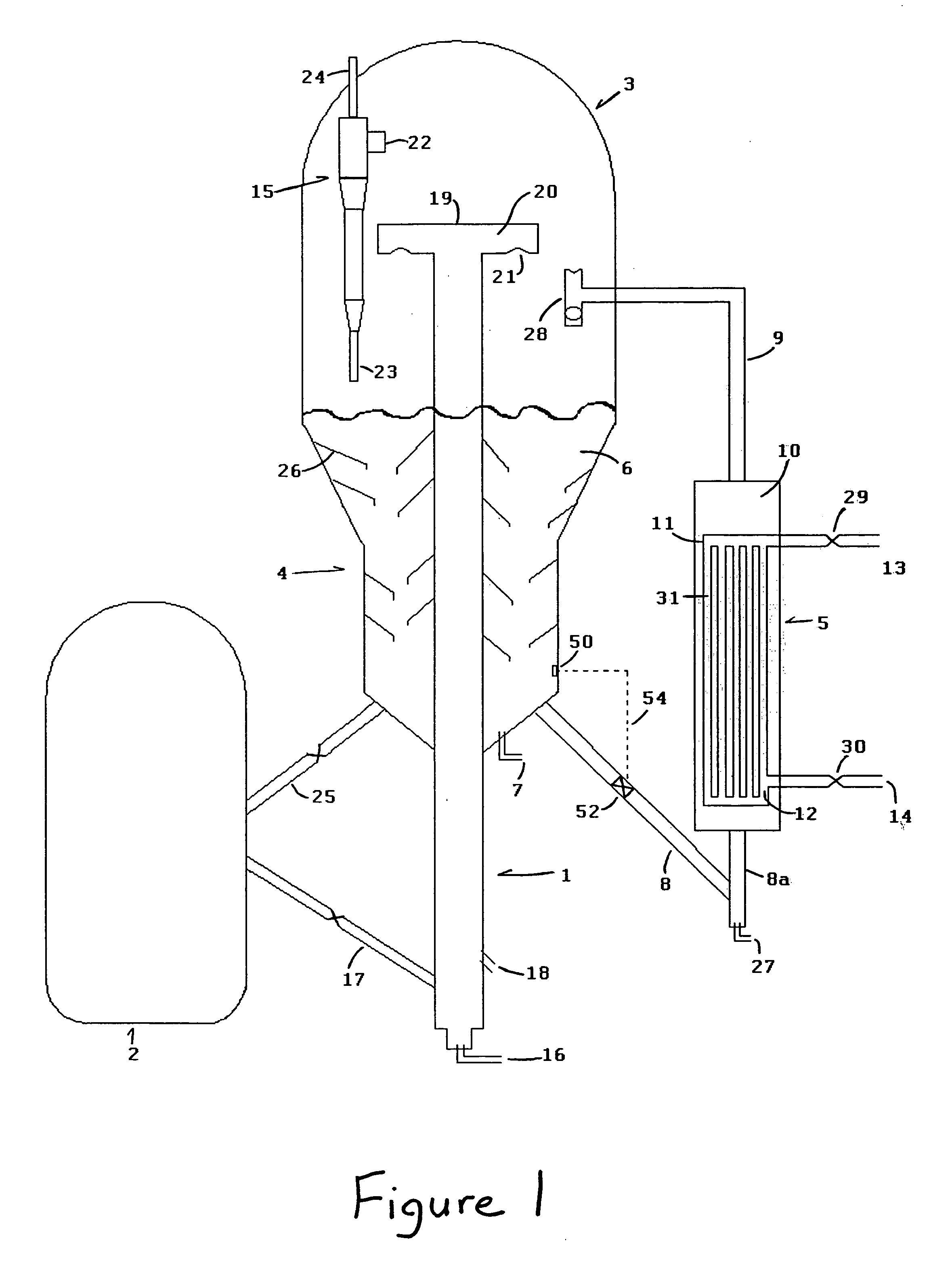
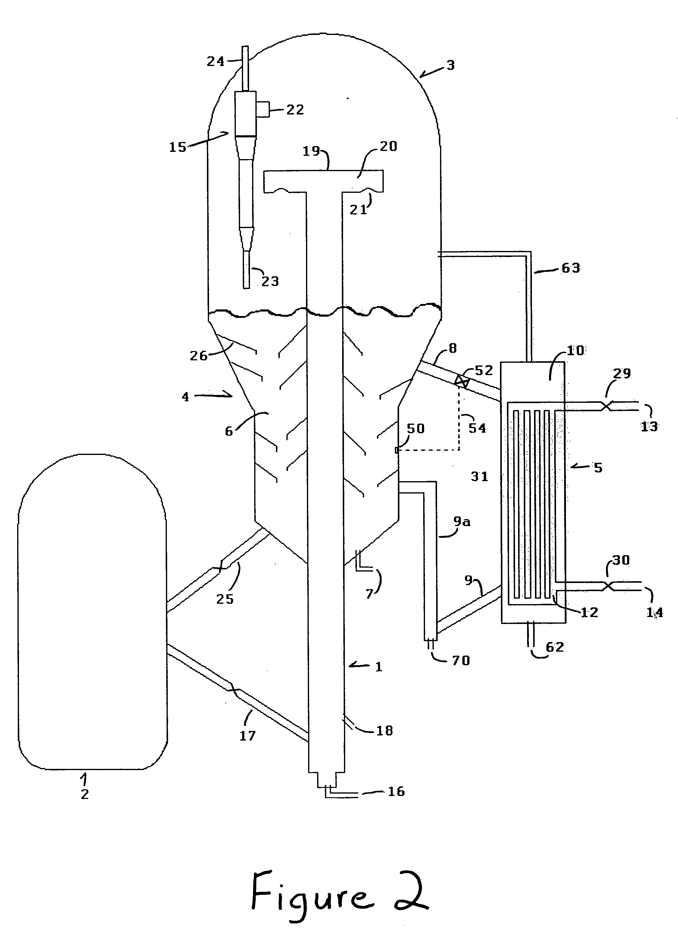
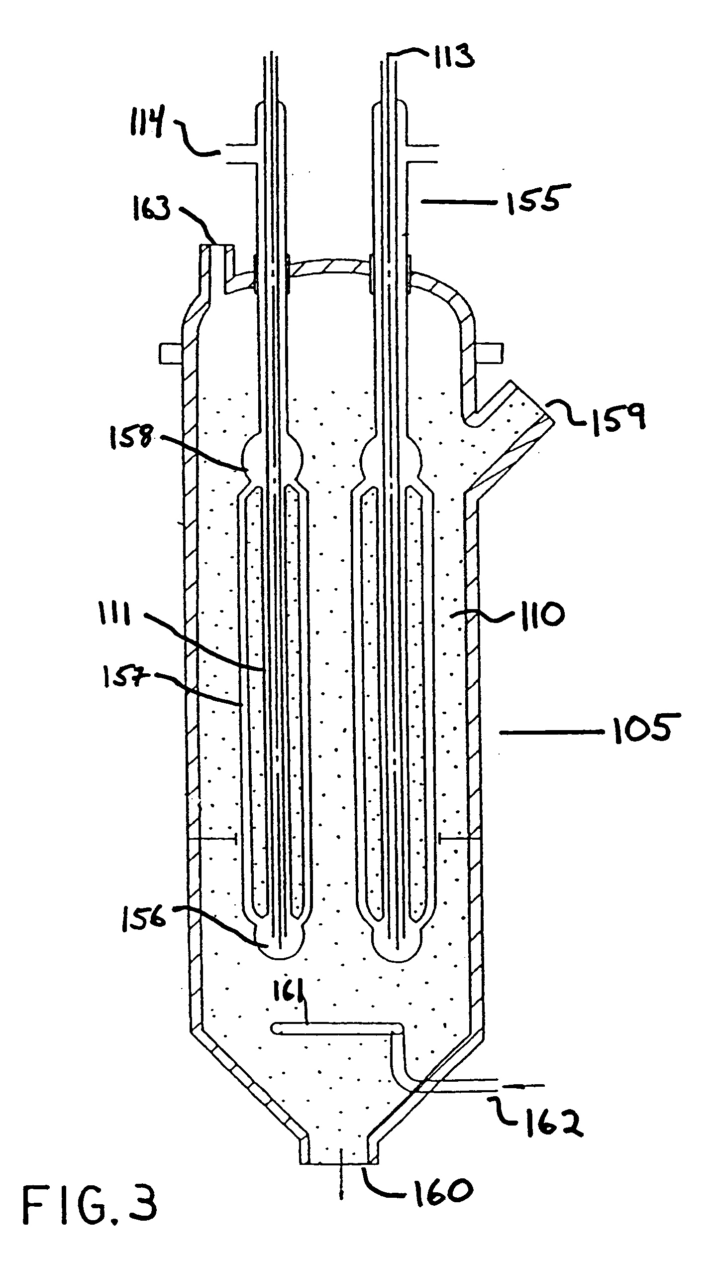
[0028] The apparatus and process of the present invention comprises a cracking reactor, a disengager, a catalyst regeneration system and a novel catalyst stripper system comprising a temperature monitoring means and a catalyst cooling means comprising a heat exchanger in flow communication with the catalyst stripper. The present process and apparatus reduces the temperature of the catalyst in the stripper zone through indirect cooling utilizing indirect heat exchange between the catalyst and a cooling liquid within the catalyst cooler.

[0029] In preferred embodiments of the present invention, the present invention has application to any of the relatively high temperature catalytic cracking operations for producing olefins in the presence of steam known to those skilled in the art. In these systems, due to the presence of steam and high temperatures, catalyst deactivation becomes a more acute problem. For example, the present invention has application to fluid catalytic cracking (FCC...


PUM

PropertyMeasurementUnit
temperatureaaaaaaaaaa

Abstract

A process and an apparatus for catalytic cracking a hydrocarbon feed to lighter hydrocarbon employing a catalyst cooler in flow communication with a catalyst stripper is disclosed.

Description

BACKGROUND OF THE INVENTION [0001] 1. Field of the Invention [0002] The present invention relates generally to a process and apparatus for prolonging the useful life of catalyst for continuous use in a high temperature fluidized catalytic cracking environment and more specifically to an apparatus and process for controlling and reducing the temperature of catalyst residing in the stripping zone to improve catalytic cracking efficiencies, extend time between catalyst replacement, and lower the environmental impact of the hydrocarbon cracking process. [0003] 2. Description of Related Art [0004] Fluidized catalytic cracking (“FCC”) processes are widely used for the conversion of hydrocarbon feed streams, such as vacuum gas oils and other relatively heavy oils, into lighter and more valuable hydrocarbon products. [0005] The basic components of the fluidized catalytic cracking unit (“FCCU”) include a reactor, a disengager, a catalyst stripper and a catalyst regenerator. The reactor inclu...

Claims


Application Information

Patent Timeline
Patent Type & Authority Applications(United States)
IPC IPC(8): B01J8/00B01J8/18B01J8/24B01J8/26B01J8/38C10G11/00C10G11/16C10G11/18C10G35/00F27B15/16
CPCB01J8/0055B01J8/0065B01J8/1809B01J8/1872B01J8/26B01J8/388C10G11/187B01J2208/00212B01J2219/002B01J2219/00202B01J2219/00231B01J2219/00236C10G11/18B01J2208/00132
Inventor LETZSCH, WARREN
Owner TECH PRECESS TECH INC
Why Eureka
Try Eureka