Al-Cu bonded structure and method for making the same

a bonded structure and cu-bonded technology, applied in the direction of solvents, manufacturing tools, transportation and packaging, etc., can solve the problems of limited enhancement of heat transfer properties obtainable from these improvements, difficult bonding of large areas or complex shapes, and restrictions on the shape and dimensions of components to be bonded, etc., to achieve stable bond characteristics, superior workability, and superior dimension characteristics

Inactive Publication Date: 2005-02-10
SUMITOMO PRECISION PROD CO LTD
View PDF8 Cites 7 Cited by
  • Summary
  • Abstract
  • Description
  • Claims
  • Application Information

AI Technical Summary

Benefits of technology

[0029] The object of the present invention is to overcome these problems in Al—Cu bonded structures and to provide an Al—Cu bonded structure and method for making the same wherein appropriate brazing conditions are selected when brazing so that stable bond characteristics are a

Problems solved by technology

However, with the significant demands made in the electronic device field regarding compactness, thin design, light weight, and high performance, there is a limit to enhance the heat transfer properties obtainable from these improvements.
With these bonding methods, however, the bonding of large areas or complex shapes is difficult, and there are restrictions on the shape and dimensions of component to be bonded whilst implementation for precision parts, e.g., electronic devices, is difficult.
This results in a brittle fracture mechanism that limits the strength of brazing joints.
When using Ag as an insert material in the Al—Cu bonding interface, however, the strength of brazing joints may not be stable depending on the br

Method used

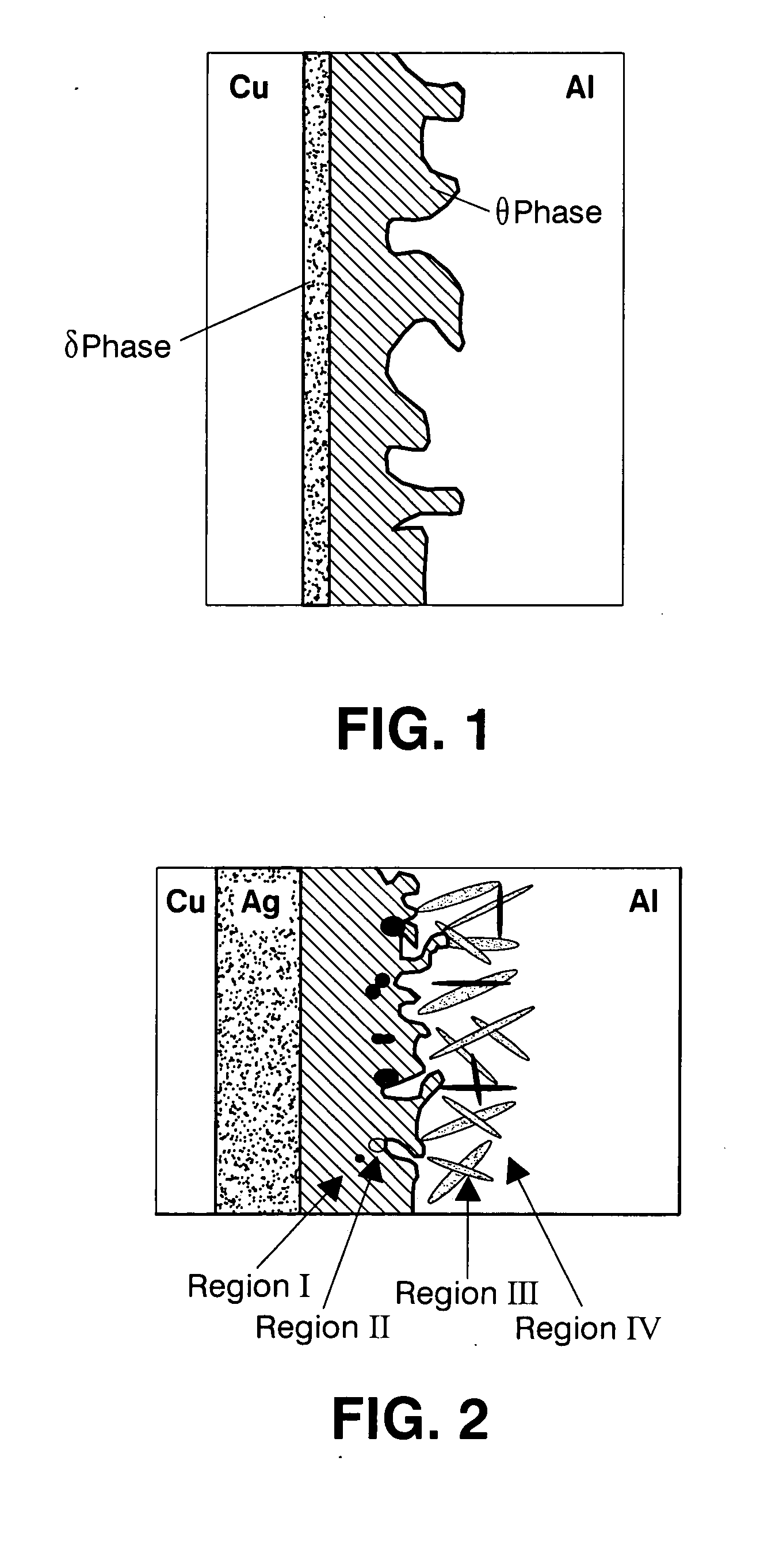
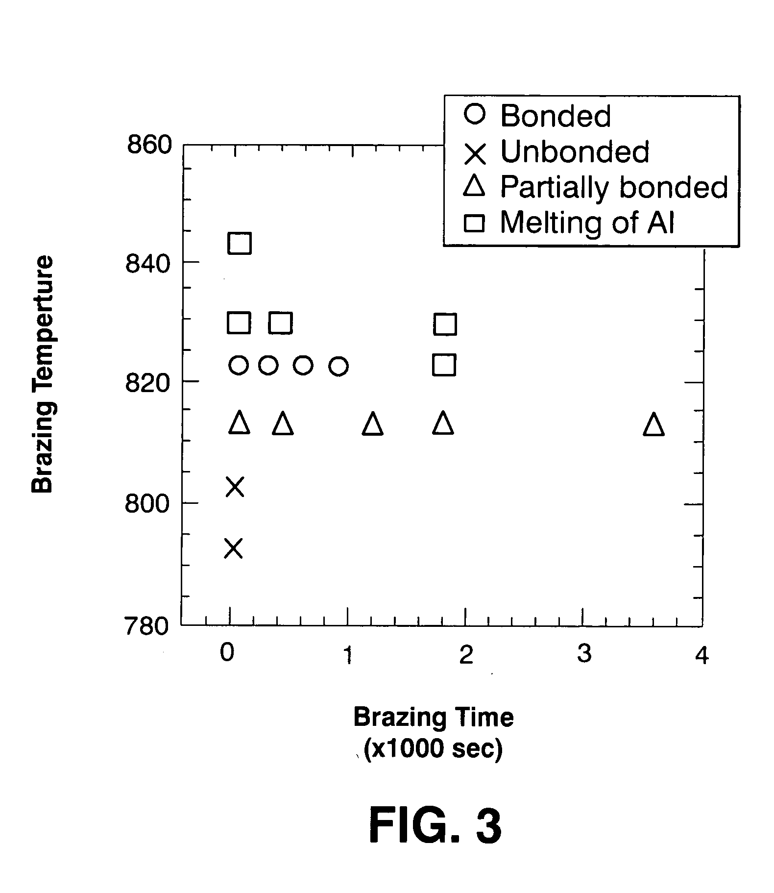
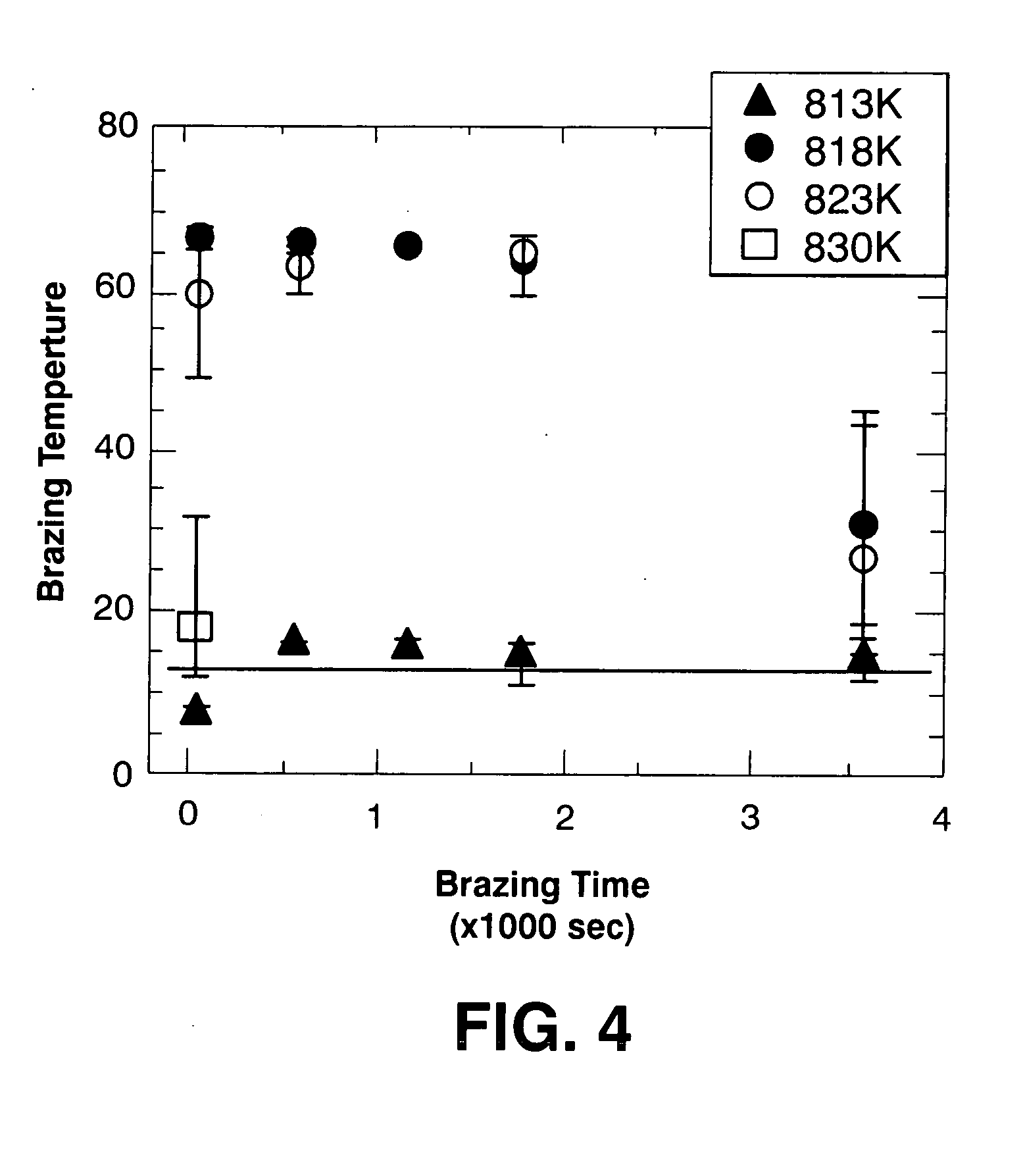

Image

  • Al-Cu bonded structure and method for making the same
  • Al-Cu bonded structure and method for making the same
  • Al-Cu bonded structure and method for making the same

Examples


1 embodiment

[0126] 2-1 Embodiment

[0127] The advantages of the thin Al—Cu bonded structure and methods for making the same according to the present invention will be described using a specific embodiment.

[0128] (1) Produce Al—Cu Bond Component

[0129] For this embodiment, a commercially available industrial pure aluminum (A1050) was used for the Al base material. The Ag used as the insert material is a pure silver foil (99.99% purity), which is clad to oxygen-free copper (C1020) and is commercially available as an Ag-clad Cu plate (Ag thickness: 100 microns, Cu thickness: 3 mm).

[0130] First, in order to form an insert layer on the surface of the Cu base material, a mirror finish is applied to the surface of the Cu base material, an Ag foil with a thickness of 100 microns is mounted so that it is in contact with the surface of the Cu base material, and solid-phase diffusion is performed. The diffusion conditions are: diffusion temperature 1038 K (765 deg C.), diffusion time 5 hr, and contact loa...


PUM

PropertyMeasurementUnit
Temperatureaaaaaaaaaa
Lengthaaaaaaaaaa
Fractionaaaaaaaaaa

Abstract

With an Al—Cu bonded structure, an Ag layer can be remained at the Al—Cu bonding interlayer, providing ductile deformation behavior and a tensile strength at the bonded interlayer similar to that of the Al base material. This results in superior bonding characteristics. Furthermore, a thin Al—Cu bonded structure can be obtained as a result of using the Al—Cu dissimilar material bonded section, which has superior workability, as the base material to perform rolling for wall-thickness reduction. The thin Al—Cu structure has superior dimensional accuracy and can meet diverse dimensional demands. The structure combines the light weight of Al with its particular heat transfer and heat dissipative characteristics and anti-corrosive properties of Cu, allowing it to meet the compact, thin, light-weight, and high-performance needs of electronic devices. The structure can be widely used in heat exchangers and heat transfer devices.

Description

CROSS-REFERENCE TO RELATED APPLICATION [0001] This application is a Continuation of International Patent Application Serial No. PCT / JP03 / 10324 filed Aug. 13, 2003.FIELD OF THE INVENTION [0002] The present invention relates to a thin bonded structure of an aluminum or aluminum alloy (“Al (aluminum)”) component and a copper or copper alloy (“Cu (copper)”) component and a method for making the same. BACKGROUND OF THE INVENTION [0003] Superior heat transfer properties and light weight are desirable in heat exchangers, heat dissipaters, heat pipes, heat sinks, and the like, which are used in electronic devices, communication devices, and transportation devices such as automobiles and aircraft. While Cu (copper) has good heat transfer and heat diffusion properties, Al (aluminum) is widely used for heat exchangers and heat transfer materials because of its light weight and heat transfer properties that are almost as good as those of Cu. [0004] More specifically, improvements for enhancing ...

Claims


Application Information

Patent Timeline
IPC IPC(8): B23K1/19B23K20/04B23K35/28B32B15/20
CPCB23K1/19B23K35/3006B23K2203/10B23K2203/12B23K2203/18Y10T428/1275B32B15/018C22C21/02Y10T428/12736Y10T428/12896B32B15/015B23K2103/10B23K2103/12B23K2103/18
Inventor KOYAMA, KENMIKI, KEIJIYOSHIDA, MAKOTOSHINOZAKI, KENJI
Owner SUMITOMO PRECISION PROD CO LTD
Why Eureka
Try Eureka