

Integrated lock, drop-box and delivery system and method
- Summary
- Abstract
- Description
- Claims
- Application Information
AI Technical Summary
Benefits of technology
Problems solved by technology
Method used
Image

Examples
second embodiment
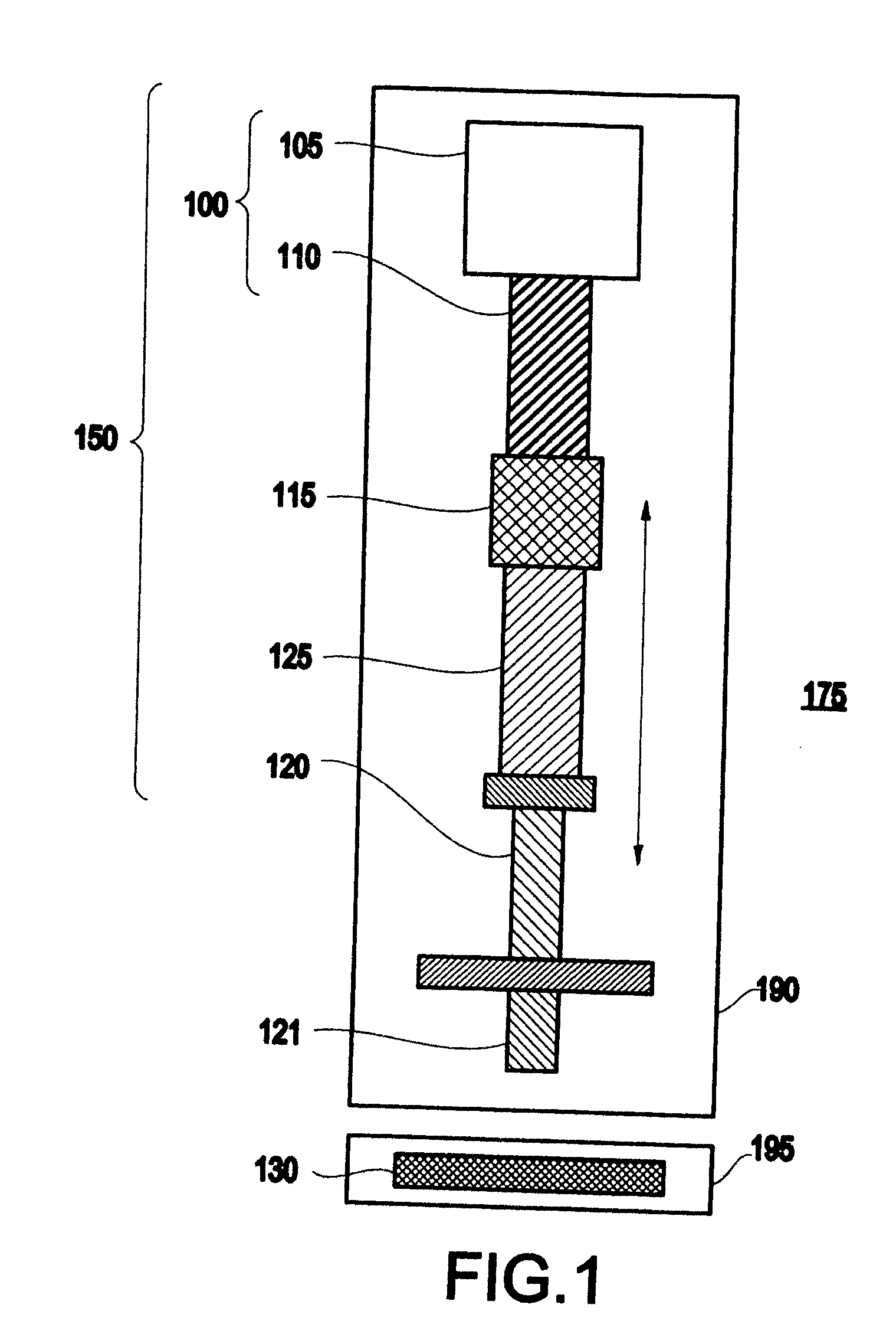
[0064] Referring again to the drawings, FIG. 1 also illustrates an electric lock 150 which may include the lock apparatus 100. Specifically, the electric lock 150 includes a drive motor 105 having a finite power supply (e.g., a battery), the drive motor 105 including a shaft and a predetermined number of windings, a threaded rod 110 axially connected to the shaft, the rod 110 including a predetermined thread pitch, a traveller 115 (e.g., a square nut) having a threaded bore which mates with the threaded rod 110 so that rotation of the threaded rod 110 causes the traveller to move along an axis of the threaded rod 110, and a lock member 120 (e.g., a hard steel bolt) contacting the traveller. The electric lock 150 may also include a tube or guide 125 (e.g., a hollow tube) through which the lock member 120 may slide back and forth. Further, the number of windings of the drive motor 105 and / or the thread pitch of the threaded rod 110 are selected to maximize a life of the finite power s...
third embodiment
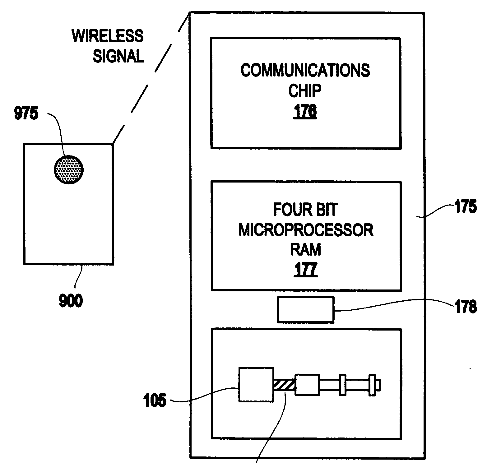
[0065] Referring again to the drawings, FIG. 1 illustrates an electric lock assembly 175 which may include the lock apparatus 100. Specifically, the assembly 175 includes a drive motor 105 connected to a first member (e.g., a door or wall of a drop-box) and having a finite power supply (e.g., a battery) 106, the drive motor 105 including a shaft and a predetermined number of windings, a threaded rod 110 axially connected to the shaft, the rod 110 including a predetermined thread pitch, a traveller 115 (e.g., a square nut) having a threaded bore which mates with the threaded rod 110 so that rotation of the threaded rod 110 causes the traveller to move along an axis of the threaded rod 110, and a lock member 120 (e.g., a hard steel bolt) contacting the traveller, the lock member having a leading end 121, and a strike 130 connected to a second member (e.g., a door or wall of a drop-box). For instance, the strike 130 may have an opening for receiving the leading end 121 of the lock memb...
fourth embodiment
[0073] Referring again to the drawings, FIG. 7A illustrates a drop-box 200 which includes the inventive electric lock assembly 175. The drop-box 200 may be similar in design and function to the drop-box disclosed by Stevens, et al., Delivery System and Method Using Electronic Tags (International App. No. PCT / US02 / 12903) and Stevens, System and Method for Unattended Delivery (International App. No. PCT / US02 / 16019) which are assigned to the present assignee and incorporated herein by reference.
[0074] The drop-box 200 may be used, for example, by couriers and post offices to pick-up and drop-off delivered parcels and mail at a location. For instance, the first member of the assembly 175 (to which the drive motor 105 is connected) may include a wall of the drop-box and the second member of the assembly 175 (to which the strike 130 is connected) may include a door of the drop box 200.
[0075] More specifically, as shown in FIG. 7A, the drop-box 200 may include a door or lid (e.g., hinged...
PUM
 Abstract
Description
Claims
Application Information