
Apparatus and method for supporting and shaping a photo-stimulable phosphor plate

a technology of phosphor plate and apparatus, which is applied in the field of computed radiography, can solve the problems of complex optics system, limiting its useful life, and reducing the lifetime and image quality, and achieves the effect of simple mechanism

Inactive Publication Date: 2005-02-10
KATZ NOA
View PDF5 Cites 15 Cited by
  • Summary
  • Abstract
  • Description
  • Claims
  • Application Information

AI Technical Summary

Benefits of technology

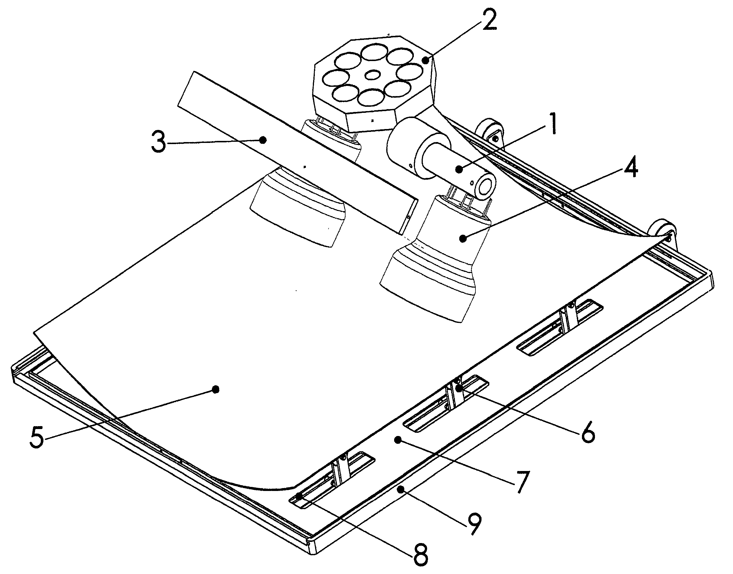
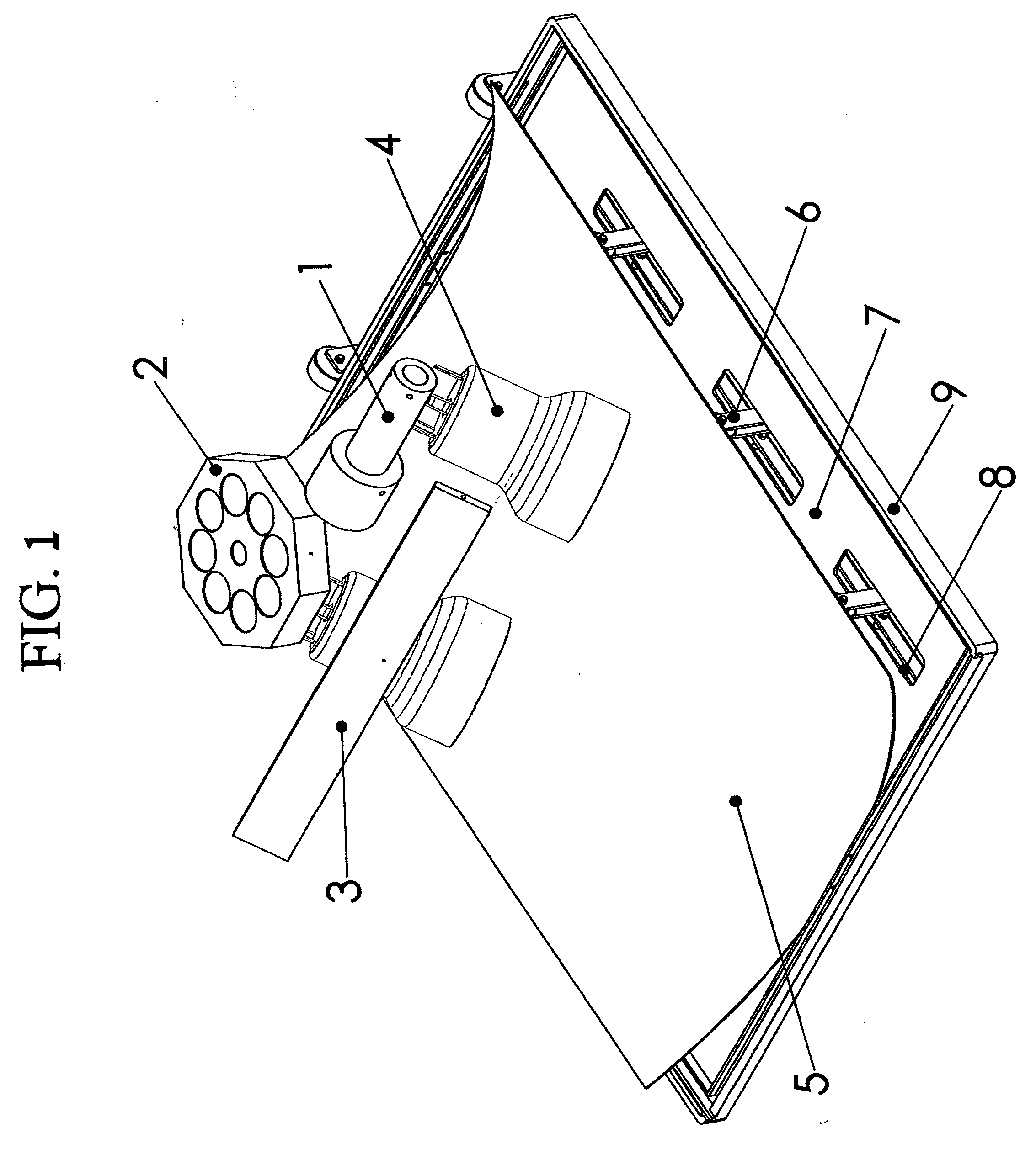
[0010] A primary object of the present invention is to provide an apparatus for loading and shaping a PSP (photostimulable phosphor plate) to a precise curved surface during scanning in a CR reader by a simple mechanism.
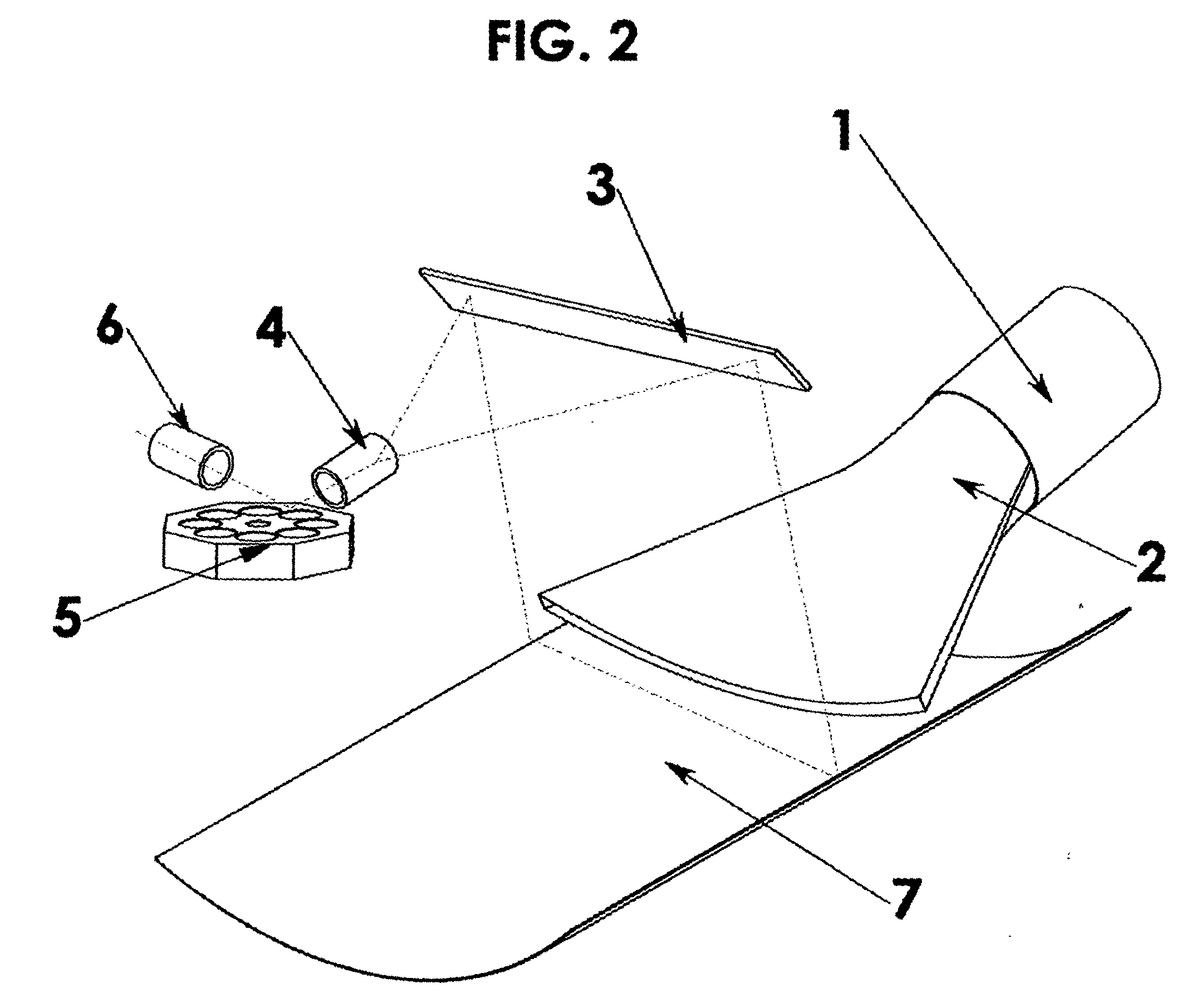
[0011] A second object of the present invention is to provide an apparatus that shapes the PSP in a way that compensates for all geometry changes which occur in the total path of the laser beam from the last lens to the target (the PSP), in order to keep the focal distance of the laser accurate and constant.
[0020] According to one embodiment, the method includes mounting a PSP in a cassette including a base adapted to receive a PSP, and a shaping element disposed in the base; causing the shaping element to permit the plate to lie flat on the base when the cassette is outside a CR reader, and causing the shaping element to lift the sides of the PSP to approximately a part-cylindrical shape, as the cassette is inserted into the CR reader.
[0021] According to another embodiment, the method includes mounting a shaping element in a scanning compartment of a CR reader, causing the shaping element to permit the PSP to lie flat in the compartment when the PSP is being scanned, and causing the shaping element to lift the sides of the PSP to approximately a part-cylindrical shape, as the PSP is scanned in the CR reader.

Problems solved by technology

Physical damage to the plate will limit its useful life.
In readers with rollers, the roller grabs the plate and can bend or rub the material, leading to reduced lifetime and image quality.
However, this arrangement requires a complex system of optics in order to scan the phosphor plate, since the stimulating laser beam must be perpendicular to the plate when it is scanned.
At present, this is accomplished by means of an Fθ lens, which is very expensive.
This system suffers from the disadvantage that the radius must be small, on the order of 90 mm, in order to achieve a compact device with a short laser path.

Method used


Image

  • Apparatus and method for supporting and shaping a photo-stimulable phosphor plate
  • Apparatus and method for supporting and shaping a photo-stimulable phosphor plate
  • Apparatus and method for supporting and shaping a photo-stimulable phosphor plate

Examples


Embodiment Construction

[0034] The present invention relates to apparatus and method for supporting and shaping a photo-stimulable phosphor plate (PSP) during scanning, wherein at least part of a PSP is shaped to an arc which is a part cylinder, and which provides a substantially unitary radial distance from a beam deflecting device to a target point of scanning. The shaping elements may be disposed in a PSP cassette, in a scanning compartment of a CR reader, adjacent an endless belt on which the PSP can be mounted, and so on.

[0035] There is also provided a cassette for a photostimulable plate (PSP) for use in a CR reader and possibly in a CR recorder. The cassette includes a base adapted to receive a PSP, and a lifting mechanism associated with two opposing sides of the base, the lifting mechanism being arranged to permit the plate to lie flat on the base when outside the CR reader, and to lift the sides of the plate to the desired shape during scanning inside the CR reader. According to one embodiment o...


PUM


Abstract

Apparatus and method for supporting and shaping a photo-stimulable phosphor plate (PSP) during scanning in a CR reader, the apparatus including elements for shaping at least part of a PSP to an arc which is a part cylinder, and which provides a substantially unitary radial distance from a beam deflecting device to a target point of scanning.

Description

FIELD OF THE INVENTION [0001] The present invention relates to Computed Radiography (CR), in general, and, in particular, to apparatus for supporting and shaping a photo-stimulable plate in a CR reader for computed radiography systems. BACKGROUND OF THE INVENTION [0002] Computed Radiography (CR) is a process for capturing digital radiographic images. CR technology has been around since the early 1980s and has been widely accepted as a digital image acquisition process that produces images equivalent to conventional x-ray film-screen systems. For exposure, a storage phosphor plate (a photo-stimulable plate, or PSP) is placed in an x-ray cassette, instead of an X-ray film sheet. The storage phosphor plate fits inside a standard film cassette and is exposed to x-rays exactly like film. [0003] Storage phosphor plates look like the intensifying screens found in conventional film-screen cassettes. However, instead of emitting light immediately when exposed to x-rays, they have the special...

Claims


Application Information

Patent Timeline
IPC IPC(8): G03B42/08
CPCG03B42/08
Inventor KATZ, NOA
Owner KATZ NOA
Learn More