Semiconductor device and a method of manufacturing the same

a technology of semiconductor devices and semiconductors, applied in the direction of semiconductor devices, basic electric elements, electrical appliances, etc., can solve the problems of increased switching loss and drive loss, and achieve the effect of reducing capacitance and reducing resistan

Inactive Publication Date: 2005-02-10
RENESAS TECH CORP
View PDF3 Cites 92 Cited by
  • Summary
  • Abstract
  • Description
  • Claims
  • Application Information

AI Technical Summary

Benefits of technology

The trench gate type power MISFET shown in FIG. 35 has a trench gate structure wherein grooves 103 are formed in a top surface of an n+type single crystal silicon substrate 101, and in an n−type single crystal silicon layer 102 formed in the upper part thereof. A conductor is embedded in each of the grooves 103 through gate insulator 104, thereby forming a gate 105. In the case of the trench gate structure described, a current flow path in the n−type single crystal silicon layer 102 which is relatively low in impurity concentration can be rendered shorter than that in a planar gate structure, thereby reducing JFET (Junction FET) resistance acting as ON-resistance. Further, a source electrode 106 may be formed to fill each of grooves 108 in the top surface of the substrate and insulating film 107, which source electrode may be electrically connected to a p+type semiconductor region 110 formed in a p−type semiconductor region 109 serving as a channel layer, wherein an n+type semiconductor region 111 serves as a source region. The p+type semiconductor region 110 can be formed by self-aligned implantation of dopant ions from the groove 108 into the substrate, so that mask alignment allowance for implantation of the dopant ions need not be taken into account. Accordingly, because MISFET cell pitches can be scaled down, higher integration of the power MISFETs can be attained, and ON-resistance can be reduced. Furthermore, with the adoption of the trench gate structure, a channel length runs along a depth of the substrate, so as to allow for scale-down of the power MISFET cell pitches as compared with the planar gate type power MISFET (in which a channel length runs along the top surface of the substrate).
However, because the groove 103 having the gate 105 formed therein is at a depth as deep as, for example, about 1 μm, the gate insulator may act as a capacitance insulator and the gate may act as a capacitance electrode. Input capacitance among the capacitance components is proportional to a length of the periphery of the groove 103 (a surface area of the groove 103 under the n+type semiconductor region 111), and feedback capacitance is proportional to a distance D 12 of a portion of the groove 103 extending from the p−type semiconductor region 109 toward the n−type single crystal silicon layer 102 (a surface area of the potion of the groove 103, in contact with the n−type single crystal silicon layer 102). Accordingly, narrowing a width of the groove 103 reduces the input capacitance, and reducing the distance D12 of the portion of the groove 103 extending from the p−type semiconductor region 109 toward the n−type single crystal silicon layer 102 (thus rendering the groove shallower) reduces feedback capacitance.
If the impurity concentration of the p−type semiconductor region 109 is raised to prevent depletion from occurring to the channel layer, the threshold voltage of the MISFET may increase, resulting in an increase in ON-resistance. Further, if the p−type semiconductor region 109 has the same depth as that of the groove 103 in order to reduce the distance of the groove 103, the bottom of the groove 103 may be covered by the p−type semiconductor region 109 due to manufacturing variation of the groove 103, and the threshold voltage of the MISFET thus increases, thereby resulting in an increase in the ON-resistance.
Thus, the present invention provides a semiconductor device and method that provides a power MISFET that simultaneously provides lower ON-resistance and lower capacitance.

Problems solved by technology

Accordingly, there is a trend for a DC-DC converter towards higher frequency, and as the DC-DC converter operates higher in frequency, an increase in switching loss and drive loss may occur in a power MISFET.

Method used


Image

  • Semiconductor device and a method of manufacturing the same
  • Semiconductor device and a method of manufacturing the same
  • Semiconductor device and a method of manufacturing the same

Examples


Embodiment Construction

It is to be understood that the figures and descriptions of the present invention have been simplified to illustrate elements that are relevant for a clear understanding of the present invention, while eliminating, for purposes of clarity, many other elements found in a typical semiconductor device and method. Those of ordinary skill in the art will recognize that other elements are desirable and / or required in order to implement the present invention. But because such elements are well known in the art, and because they do not facilitate a better understanding of the present invention, a discussion of such elements is not provided herein. The disclosure herein is directed to all such variations and modifications to the applications, networks, systems and methods disclosed herein and as will be known, or apparent, to those skilled in the art.

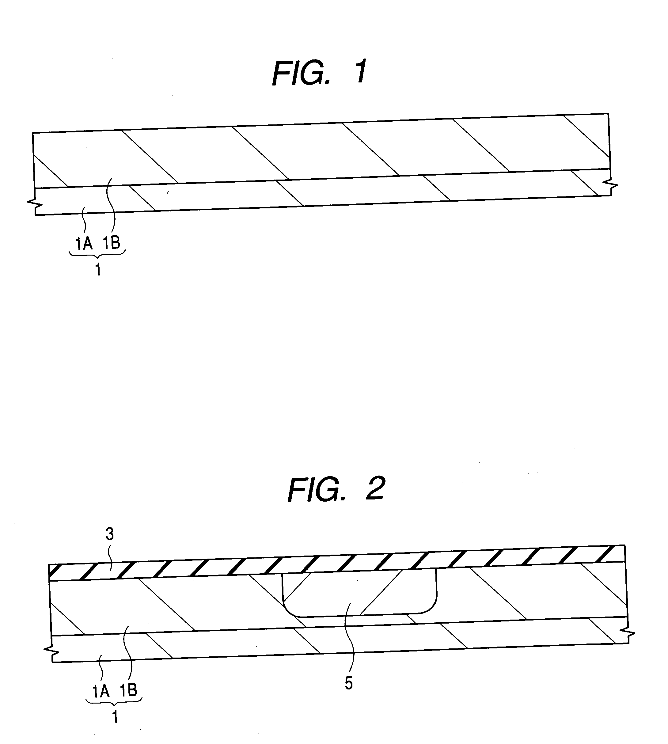
As shown in FIG. 1, a semiconductor substrate (hereinafter also referred to as a substrate) 1 is provided. An n−type single crystal silicon ...


PUM


Abstract

A technology is provided to reduce ON-resistance, and the prevention of punch through is achieved with respect to a trench gate type power MISFET. Input capacitance and a feedback capacitance are reduced by forming a groove in which a gate electrode is formed so as to have a depth as shallow as about 1 μm or less, a p−type semiconductor region is formed to a depth so as not to cover the bottom of the groove, and a p-type semiconductor region higher in impurity concentration than the p−type semiconductor region is formed under a n+type semiconductor region serving as a source region of the trench gate type power MISFET, causing the p-type semiconductor region to serve as a punch-through stopper layer of the trench gate type power MISFET.

Description

CROSS-REFERENCE TO RELATED APPLICATION The present application claims priority from Japanese Patent application JP 2003-286142 filed on Aug. 4, 2003, the content of which is hereby incorporated by reference as if set forth in the entirety herein. FIELD OF THE INVENTION The invention relates to a semiconductor device and for a method of manufacturing the same, and in particular, to a semiconductor device and method employing power MISFETs (Metal Insulator Semiconductor Field Effect Transistors). BACKGROUND OF THE INVENTION In the case of a trench (groove) gate type power MOSFET (Metal Oxide Semiconductor Field Effect Transistor) formed in a structure incorporating, for example, a p-type epitaxial layer as an upper layer of an n+type substrate, it is known to reduce the risk of punch-through breakdown of the trench gate by forming an n-type drain region extended between the n+type substrate and the bottom of a trench, and by forming a junction of the n-type drain region and the p-t...

Claims


Application Information

Patent Timeline
Patent Type & Authority Applications(United States)
IPC IPC(8): H01L21/265H01L29/78H01L21/336H01L29/08H01L29/10H01L29/423H01L29/45H01L29/49
CPCH01L21/26586H01L29/1095H01L2924/1305H01L2924/1306H01L2924/13062H01L2224/0603H01L2224/05552H01L2924/13091H01L24/05H01L29/4236H01L29/4238H01L29/456H01L29/4925H01L29/4933H01L29/7813H01L29/41766H01L29/66727H01L29/66734H01L29/7811H01L29/0878H01L2924/00
Inventor SHIRAISHI, MASAKINAKAZAWA, YOSHITO
Owner RENESAS TECH CORP
Why Eureka
Try Eureka