Switching media converter and ring type wavelength division multiplexing passive optical network system using the same

a technology of wavelength division multiplexing and optical network, applied in data switching networks, multiplex communication, electromagnetic repeaters, etc., can solve the problems of complex and expensive b-adm ring networks using b-adms, unidirectional early development of wdm ring architecture, etc., and achieve the effect of simplifying the architecture of the central offi

Inactive Publication Date: 2005-02-10
JUN KOOK CHOI
View PDF8 Cites 34 Cited by
  • Summary
  • Abstract
  • Description
  • Claims
  • Application Information

AI Technical Summary

Benefits of technology

[0015] Therefore, an object of the present invention is to provide a ring type WDM PON system using the same wavelength for forward and backward channels, which has a single fiber bi-directional ring architecture, thereby being capable of simplifying the architecture of its central office while ensuring a desired redundancy.

Problems solved by technology

Early developed WDM ring architectures were unidirectional.
However, this self-healing system has a problem of an increase in the fiber installation costs caused by the double fiber ring architecture.
Also, the above mentioned single fiber bi-directional ring networks using B-ADMs are complex and expensive while having a problem in that new type optical elements should be used.
However, such an Ethernet system has not been practically applied to backbone networks because it does not have a self-healing function coping with disaster or other network disabling statuses, so that it does not have a verified reliance.
However, the above mentioned ring type WDM PON system has a drawback in that the architecture of the central office CO is complex because two transmitting / receiving modules for each wavelength and two multiplexers / demultiplexers are used to provide a redundancy for coping with fiber breakage or failure of a laser diode (LD) (corresponding to a transmitter) or photodiode (PD) (corresponding to a receiver) associated with a particular channel.
Where the above mentioned ring type network architecture is configured to have a redundancy for all nodes, there may be problems in terms of costs and functions.

Method used


Image

  • Switching media converter and ring type wavelength division multiplexing passive optical network system using the same
  • Switching media converter and ring type wavelength division multiplexing passive optical network system using the same
  • Switching media converter and ring type wavelength division multiplexing passive optical network system using the same

Examples


Embodiment Construction

[0029] Now, preferred embodiments of the present invention will be described in detail with reference to the annexed drawings. In the following description of the present invention, a detailed description of known functions and configurations incorporated herein will be omitted when it may make the subject matter of the present invention rather unclear.

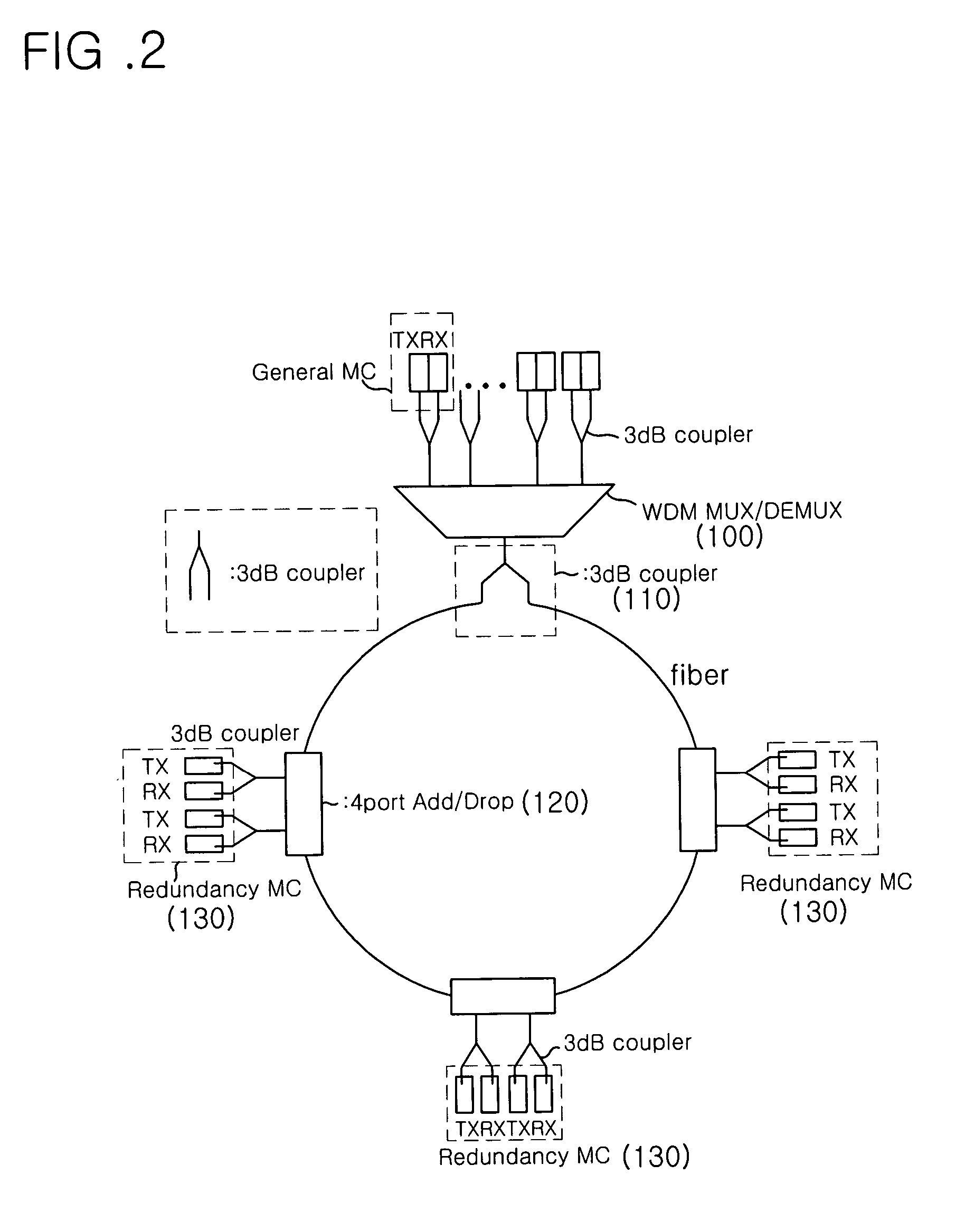
[0030]FIG. 2 is a schematic diagram illustrating the configuration of a ring type WDM PON system using the same wavelength for forward and backward channels in accordance with an embodiment of the present invention. FIG. 3 is a schematic diagram illustrating the configuration of a 4-port add / drop device 120 shown in FIG. 2. FIG. 4 is a schematic diagram illustrating a detailed configuration of a switching media converter 130 for a redundancy purpose shown in FIG. 2.

[0031] Referring to FIG. 2, the ring type WDM PON system according to the illustrated embodiment of the present invention includes a central office (CO), and bi-direction...


PUM


Abstract

Disclosed is a ring type wavelength division multiplexing (WDM) passive optical network (PON) system using the same wavelength for forward and backward channels while inexpensively implementing a redundancy function, and a switching media converter usable in the ring type WDM PON system. The WDM PON system provided a redundancy function to each node, so that the central office of the system can have a simplified architecture. Accordingly, there is an advantage in that the construction costs of the central office can be reduced. And, the network construction costs can be minimized because it is possible to provide a desired redundancy to a part of the nodes, taking into consideration the significance of each node.

Description

BACKGROUND OF THE INVENTION [0001] 1. Field of the Invention [0002] The present invention relates to a wavelength division multiplexing (WDM) passive optical network (PON) system, and more particularly to a ring type WDM PON system using the same wavelength for forward and backward channels while inexpensively implementing a redundancy function, and a switching media converter usable in the ring type WDM PON system. [0003] 2. Description of the Related Art [0004] A WDM system is known as a system in which different wavelengths are assigned to respective subscribers by a central office (CO) so that the central office can simultaneously transmit data to the subscribers. Respective subscribers can transmit data, using different wavelengths assigned thereto. This system has advantages in that it can provide a large quantity of information to each subscriber while maintaining a high security and easily achieving an improvement in performance. [0005] Also, a PON is known which has an arch...

Claims


Application Information

Patent Timeline
Patent Type & Authority Applications(United States)
IPC IPC(8): H04B10/03H04B10/032H04B10/035H04B10/077H04B10/27H04B10/272H04B10/275H04B10/29H04J3/16H04J14/00H04J14/02H04L12/42H04L12/437H04L12/44H04Q11/00
CPCH04J14/0206H04J14/0213H04J14/0216H04J14/0227H04J14/0282H04J14/0283H04J14/0246H04J14/029H04J14/0294H04J14/0297H04Q11/0067H04Q2011/0081H04Q2011/0092H04J14/0287H04L12/42
Inventor CHOI, JUN-KOOKLEE, SO-YOUNGKANG, SEUNG-MIN
Owner JUN KOOK CHOI
Why Eureka
Try Eureka