Linear compressor and apparatus to control the same

a compressor and linear technology, applied in the direction of motor/generator/converter stopper, dynamo-electric converter control, pump parameter, etc., can solve problems such as deteriorating energy efficiency, and achieve the effect of maximising the efficiency of the linear compressor

Inactive Publication Date: 2005-02-10
SAMSUNG ELECTRONICS CO LTD
View PDF18 Cites 93 Cited by
  • Summary
  • Abstract
  • Description
  • Claims
  • Application Information

AI Technical Summary

Benefits of technology

[0007] Accordingly, it is an aspect of the present invention to provide a linear compressor and apparatus to control the linear compressor, which allows a frequency of a drive current of the line...

Problems solved by technology

Generally, since a reciprocating compressor converts a rotary motion of a motor into a linear motion to operate ...

Method used


Image

  • Linear compressor and apparatus to control the same
  • Linear compressor and apparatus to control the same
  • Linear compressor and apparatus to control the same

Examples


first embodiment

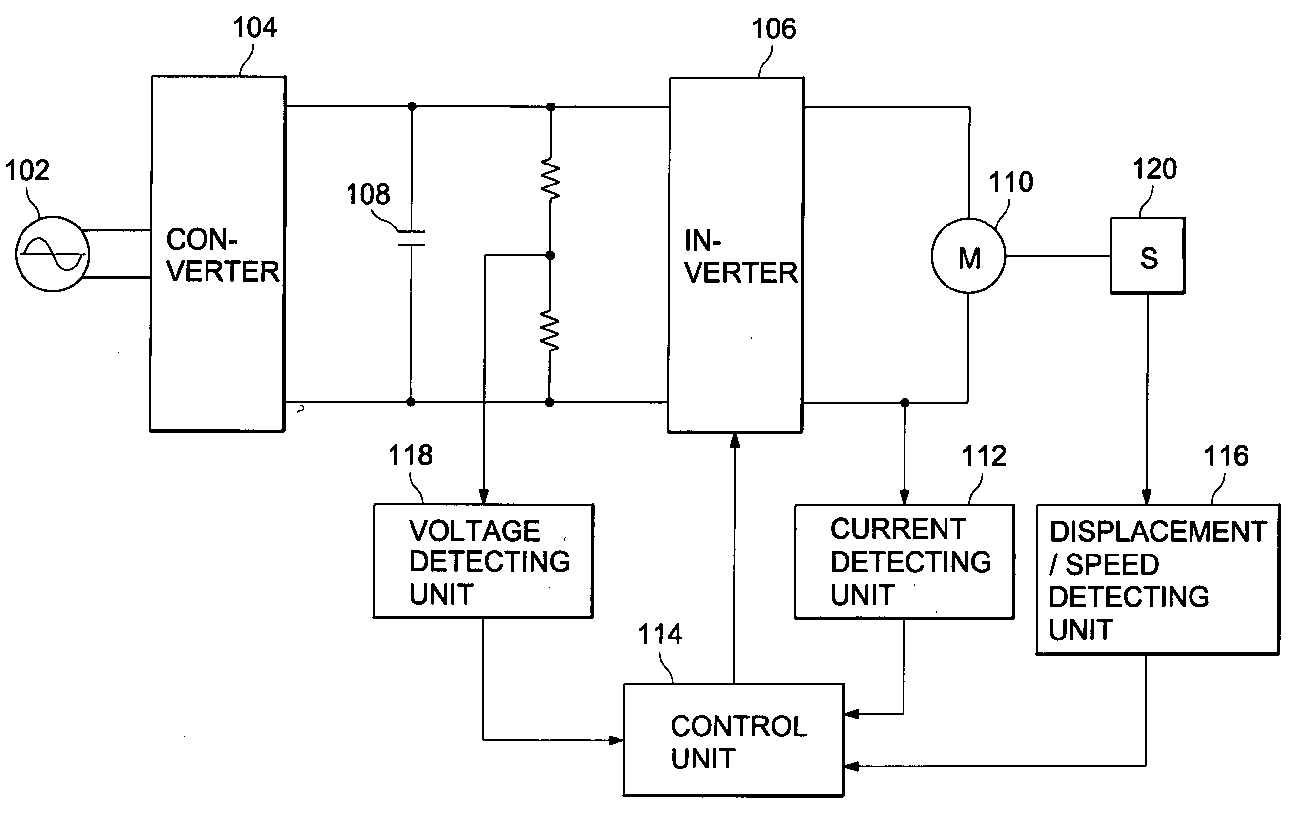
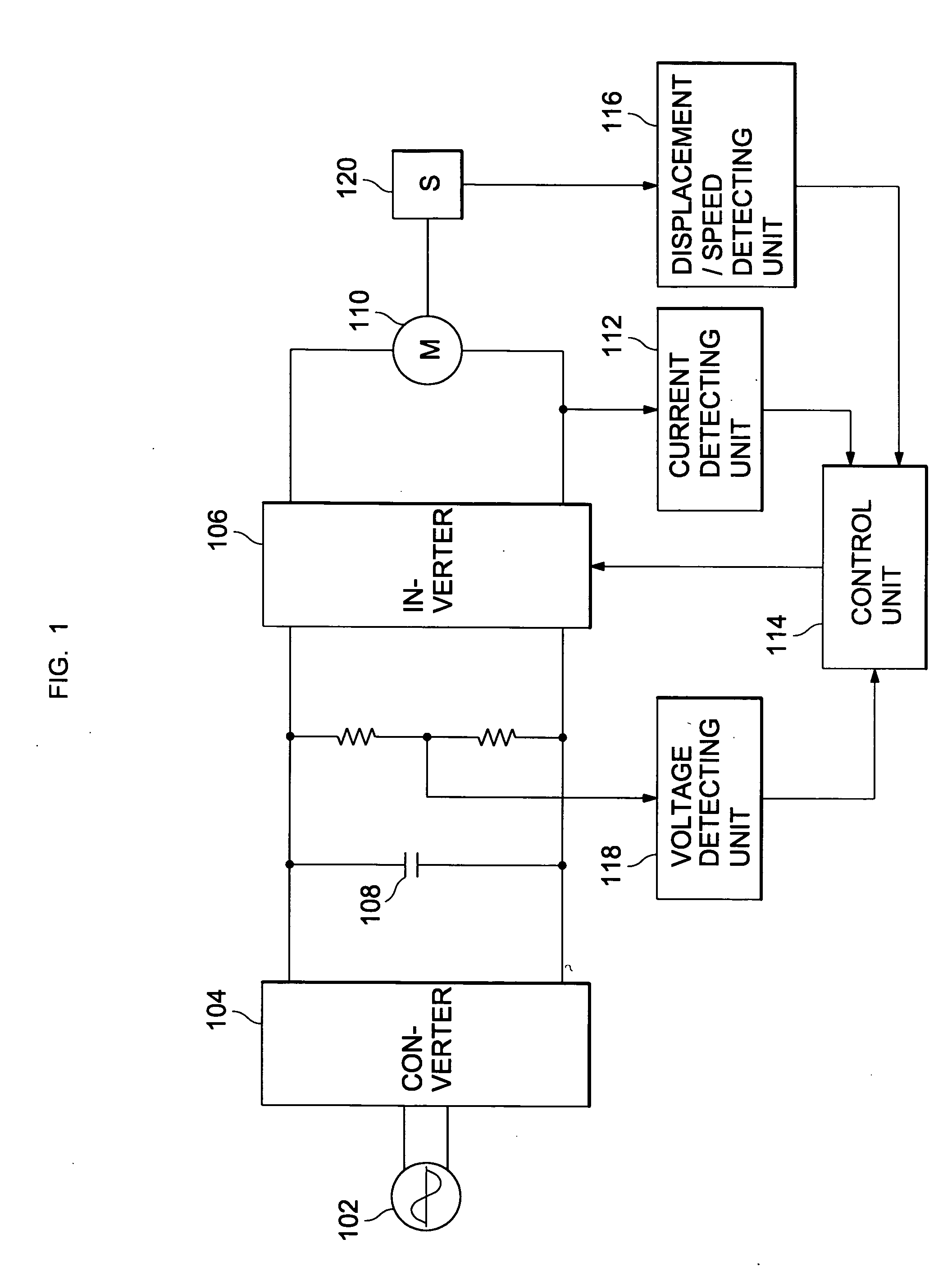
[0021] FIGS. 1 to 4 are views showing a linear compressor and apparatus to control the linear compressor, according to the present invention, which illustrates a case in which a displacement and a speed of a piston are detected through a displacement sensor, and a mechanical resonance frequency of the linear compressor is obtained using the detected displacement and the detected speed.

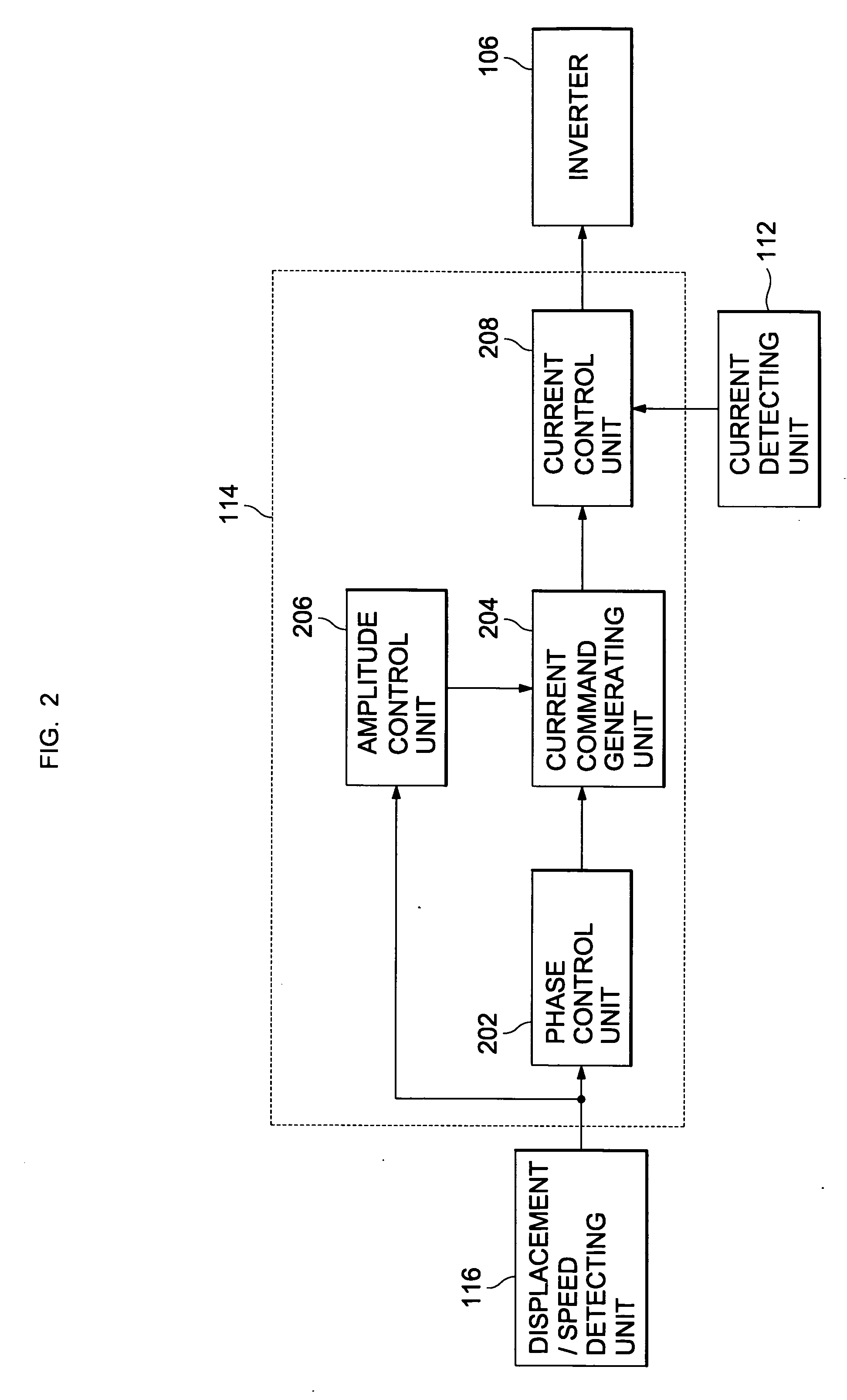
[0022]FIG. 1 is a block diagram of an apparatus controlling a linear compressor, according to the first embodiment of the present invention. As shown in FIG. 1, a converter 104 converts alternating current (AC) power supplied from an AC power source 102 into direct current (DC) power. An inverter 106 connected to the converter 104 through a DC coupling capacitor 108 generates AC power with a variable voltage level and / or a variable frequency required to drive a linear motor 110.

[0023] An input terminal and an output terminal of the inverter 106 are connected to a voltage detecting unit 118 and a curre...

second embodiment

[0031]FIGS. 5 and 6 are views showing an apparatus controlling a linear compressor, according to the present invention, which illustrates a case in which a displacement and a speed of a mover of a drive motor (linear motor) are indirectly detected using electrical characteristic values of the linear motor instead of using a displacement sensor, and a mechanical resonance frequency of the linear compressor is obtained using the indirectly detected displacement and the speed.

[0032]FIG. 5 is a block diagram of an apparatus controlling a linear compressor, according to a second embodiment of the present invention. As shown in FIG. 5, a displacement / speed detecting unit 502 generates displacement / speed waveforms of a piston using a drive current detected by a current detecting unit 112, a DC voltage supplied to an inverter 106 and detected by a voltage detecting unit 118, and electrical characteristic values of a linear motor 110. As is described above, a control unit 514 controls the dr...


PUM


Abstract

A linear compressor and apparatus to control the linear compressor are provided which allows a frequency of a drive current supplied to a drive motor to synchronize with a resonance frequency varying according to a load fluctuation, in real time, thus obtaining a maximum efficiency of the linear compressor. The linear compressor includes a drive motor, a piston reciprocating by the drive motor and a control unit generating a reference current having a phase difference of 90° with respect to a displacement waveform of the piston and a frequency equal to the displacement waveform of the piston, and controls a drive current supplied to the drive motor to synchronize with a resonance frequency of the piston by synchronizing the drive current with the reference current.

Description

CROSS-REFERENCE TO RELATED APPLICATION [0001] This application claims the benefit of Korean Patent Application No. 2003-53779, filed Aug. 4, 2003 in the Korean Intellectual Property Office, the disclosure of which is incorporated herein by reference. BACKGROUND OF THE INVENTION [0002] 1. Field of the Invention [0003] The present invention relates, in general, to linear compressors and, more particularly, to a linear compressor in which a piston is linearly reciprocated by a linear motor, and an apparatus to control the linear compressor. [0004] 2. Description of the Related Art [0005] Generally, since a reciprocating compressor converts a rotary motion of a motor into a linear motion to operate a piston, an energy loss occurs during a motion conversion procedure, thus deteriorating an energy efficiency thereof. Different from that of the reciprocating compressor, a linear compressor uses a linear motor in which a mover linearly reciprocates, so that a linear motion of a piston is di...

Claims


Application Information

Patent Timeline
IPC IPC(8): F04B35/04F04B49/06F04B17/04H02P25/06
CPCF04B35/045F04B49/065F04B2203/0402F04B2203/0401F04B2201/0202F04B17/04F04B35/04F04B49/06
Inventor LEE, KWANG WOON
Owner SAMSUNG ELECTRONICS CO LTD
Why Eureka
Try Eureka