Method for splinting rib injuries

a rib and splinting technology, applied in fractures, medical science, non-surgical orthopedic devices, etc., can solve problems such as difficult to adjust the patch, difficult to shower, and the task is beyond the skill of most patients, and achieves low manufacturing cost of the rib splint, simple construction, and maximum patient comfort.

Inactive Publication Date: 2005-02-10
ROLNICK MICHAEL ALAN +2
View PDF5 Cites 12 Cited by
  • Summary
  • Abstract
  • Description
  • Claims
  • Application Information

AI Technical Summary

Benefits of technology

[0016] The disclosed rib splinting method provides stabilization to the side of the rib cage having the injured ribs only. Expansion of the uninjured side is not impeded by the device. The splint provides a stabilizing force to the injury site even during minimal chest expansion, and may be adjusted after application to maximi...

Problems solved by technology

Rib injuries present a unique splinting challenge due to their location.
However, this proves unsatisfactory because the brace significantly limits lung expansion (both lungs), is associated with high rates of post-injury pneumonia, and is uncomfortable for the patient.
However, it is suboptimal because the amount of reducing force applied to...

Method used


Image

  • Method for splinting rib injuries
  • Method for splinting rib injuries
  • Method for splinting rib injuries

Examples


Embodiment Construction

[0025] As used herein, medial is defined as the direction toward the center of the body of a patient, and lateral is defined as the direction away from the center of the body.

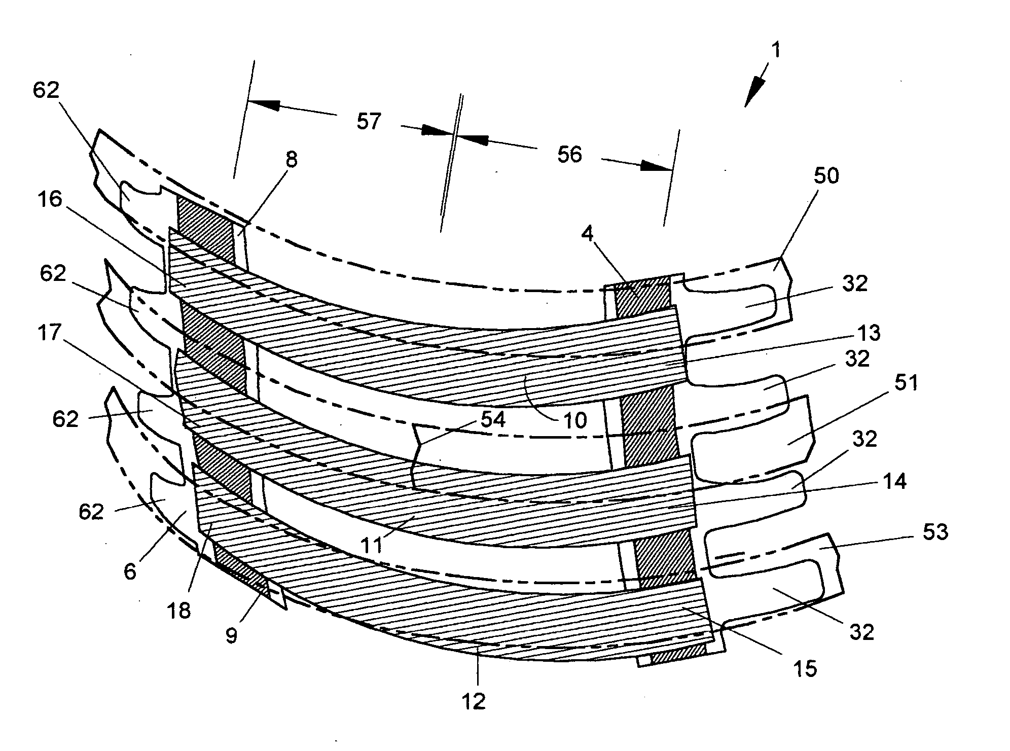
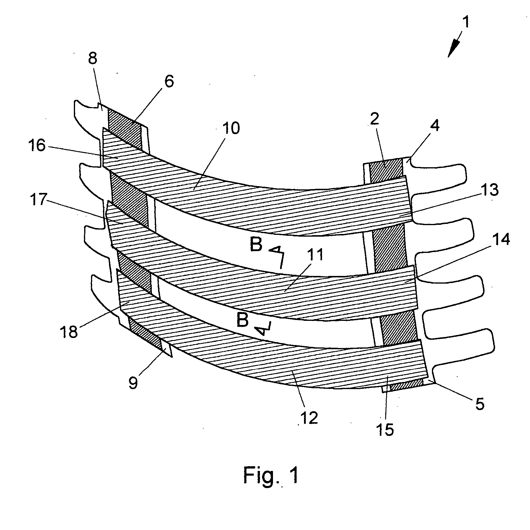
[0026] Referring to the Figures, as best seen in FIG. 1, Rib Splint 1 comprises a more or less vertical, medial anchor strip 2 having an upper end 4 and a lower end 5 and a lateral anchor strip 6 having an upper end 8 and a lower end 9. Splint 1 also comprises a plurality of more or less horizontal elastomeric straps 10, 11, and 12 having medial ends 13, 14 and 15 respectively and lateral ends 16, 17 and 18 respectively, the medial ends being removably attached to medial anchor strip 2, and the lateral ends being removably attached to lateral anchor strip 6. Three elastomeric straps are shown, however, the actual number used will depend on the injury being treated and may be more or less.

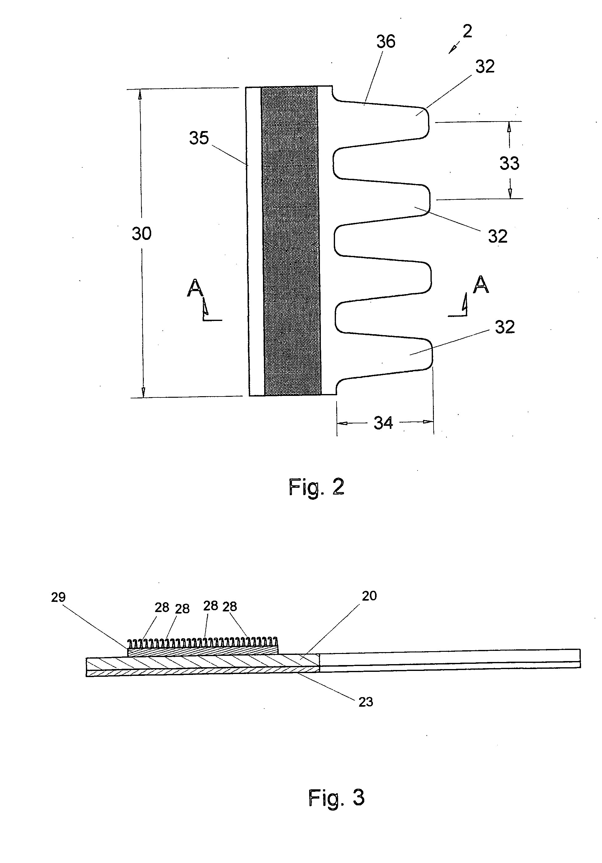
[0027] Referring to FIGS. 2 and 3, medial anchor strip 2 of length 30 has a lateral edge 35 and a medial edge 36 which form...


PUM


Abstract

A method for splinting rib injuries is disclosed. A pair of anchor strips having a plurality of fasteners on their exposed surfaces are attached to the skin of the chest cavity by an adhesive, the strips being more or less vertically oriented and equidistantly spaced from the injury. Elastomeric straps having a plurality of fastener receivers are removably fastened to the anchor strips across the injury so as to produce a stabilizing/reducing force at the injury. Tension in the straps and orientation of the straps are adjusted to maximize patient comfort. In another embodiment a pad is placed between the elastomeric straps and the chest wall. In other embodiments the pad is a hot or cold compress. In yet another embodiment the pad is connected to a cold therapy machine.

Description

[0001] This application claims the benefit of provisional application 60 / 442,601 filed Jan. 27, 2003.BACKGROUND OF THE INVENTION [0002] The present invention relates to stabilizing / splinting fractures of bones, bone contusions, and sprains. More specifically it relates to the splinting of rib injuries. [0003] Patients with blunt chest trauma are frequently seen in hospital emergency departments. Major initial concerns for the treating physician are lung collapse, which is ruled out by a chest x-ray, and other injuries that can be ruled out with a combination of physical exam and possibly other imaging studies. Once the evaluation is completed, the majority of patients are discharged home with narcotic pain medications and an incentive spirometer, a device used by the patient to monitor the volume of air inhalation during breathing. An incentive spirometer is imperative for chest wall injuries because it helps to facilitate maximal lung expansion, thereby minimizing the chance of min...

Claims


Application Information

Patent Timeline
IPC IPC(8): A61F5/03A61F5/058
CPCA61F5/058A61F5/03
Inventor ROLNICK, MICHAEL ALANWARDEN, MATTHEW PERRYVAN WYK, ROBERT ALLEN
Owner ROLNICK MICHAEL ALAN
Why Eureka
Try Eureka