Cervical plate for stabilizing the human spine

a cervical plate and vertebrae technology, applied in the field of orthopedic bone fixation devices, can solve the problems of life-threatening traumatic injuries, increased degenerative change rate, and damage at the upper end of the lumbar spin

Inactive Publication Date: 2005-02-10
ORTHO DEV CORP
View PDF99 Cites 327 Cited by
  • Summary
  • Abstract
  • Description
  • Claims
  • Application Information

AI Technical Summary

Problems solved by technology

Trauma frequently results in damage at the upper end of the lumbar spine, where the mobile lumbar segments join the less mobile dorsal spine.
Excessive forces on the spine not only produce life-threatening traumatic injuries, but may contribute to an increased rate of degenerative change.
Because the neck has a wide range of motion and is the main support for the head, the neck is extremely vulnerable to injury and degeneration.
Generally, a constrained plate completely immobilizes the vertebrae and does not allow for graft settling.
A common problem associated with the use of bone fixation plates is the tendency for bone screws to become dislodged and “back out” from the bone, thereby causing the plate to loosen.
However, many of these attempts have resulted in a bone fixation plate having a very large profile and size that can cause irritation and discomfort in the patient's spinal region, or an assembly with multiple parts that must be assembled prior to implantation, which can be laborious and time consuming for surgeons.
Due to its relative lo...

Method used


Image

  • Cervical plate for stabilizing the human spine
  • Cervical plate for stabilizing the human spine
  • Cervical plate for stabilizing the human spine

Examples


Embodiment Construction

[0034] For the purposes of promoting an understanding of the principles in accordance with the disclosure, reference will now be made to the embodiments illustrated in the drawings and specific language will be used to describe the same. It will nevertheless be understood that no limitation of the scope of the disclosure is thereby intended. Any alterations and further modifications of the inventive features illustrated herein, and any additional applications of the principles of the disclosure as illustrated herein, which would normally occur to one skilled in the relevant art and having possession of this disclosure, are to be considered within the scope of the disclosure claimed.

[0035] Before the present device and methods for implantation of said device are disclosed and described, it is to be understood that this disclosure is not limited to the particular configurations, process steps, and materials disclosed herein as such configurations, process steps, and materials may var...


PUM


Abstract

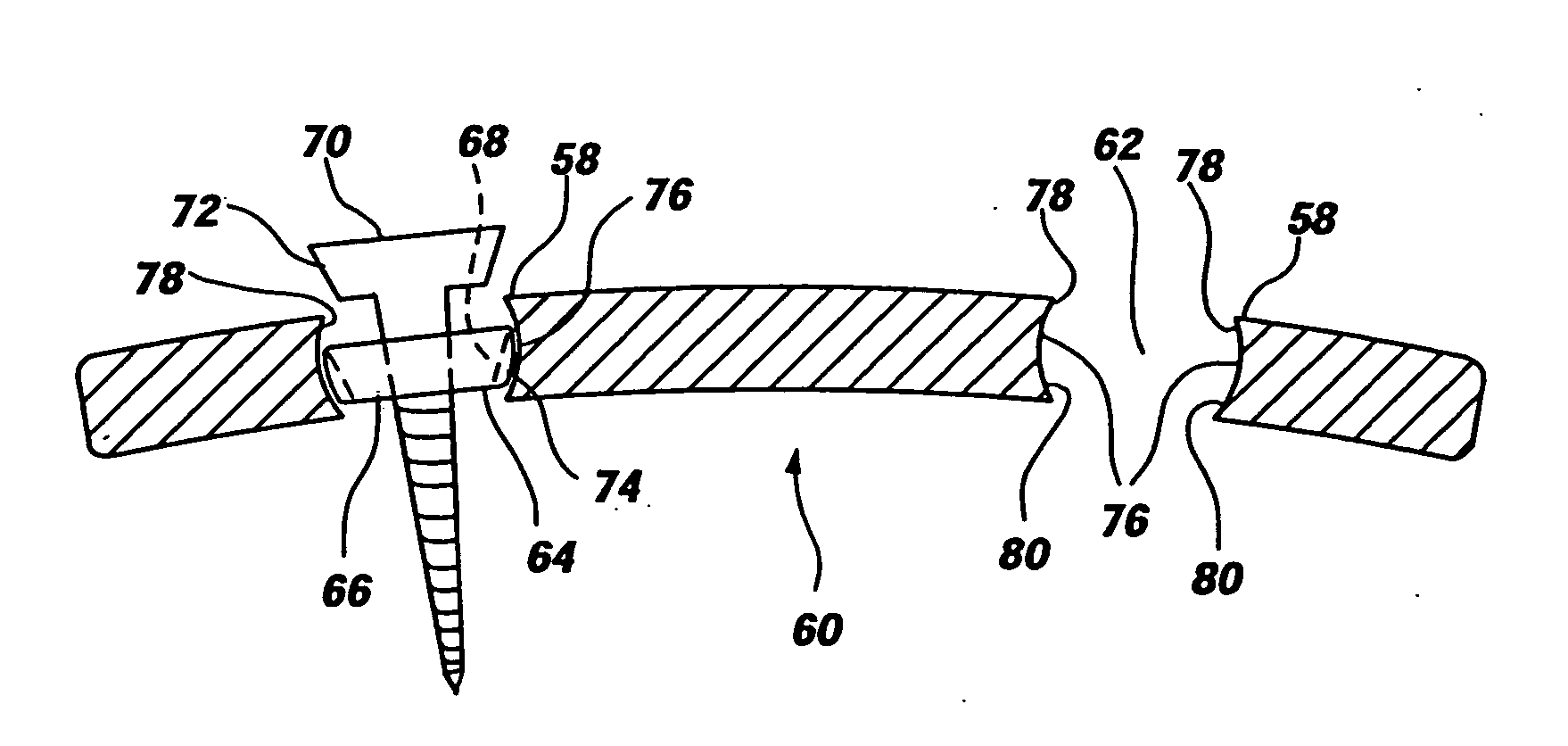
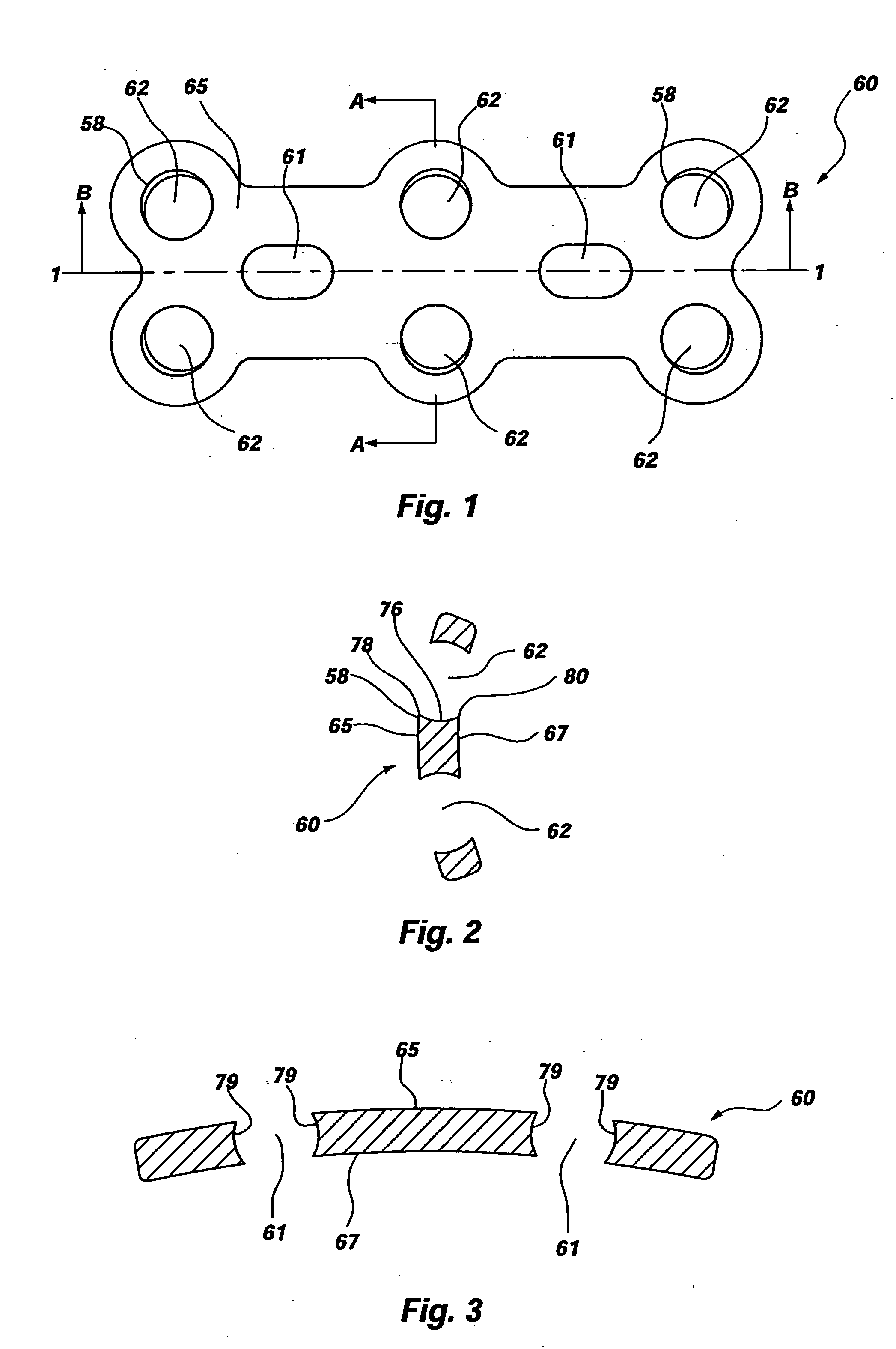
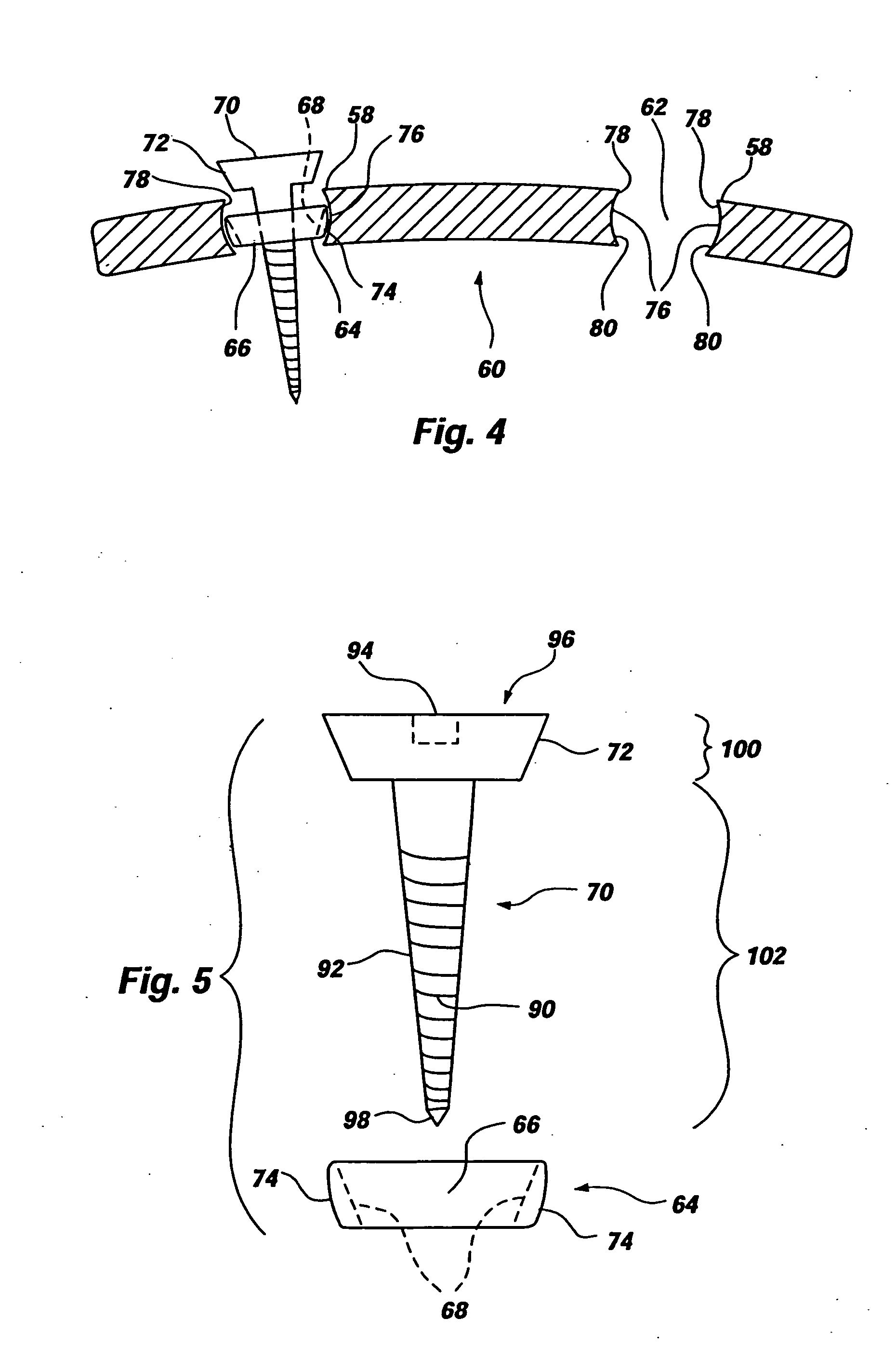
A dynamic spinal fixation plate assembly includes a spinal plate, a receiving member, and a fastener resulting in a low profile orthopedic device. The plate may comprise a hole for maintaining the receiving member. The relationship between the receiving member and the plate may allow the plate to adjust during graft settling. The receiving member may be locked to the plate utilizing the mechanical or chemical properties of the device, or the receiving member may be configured to move and rotate freely within the plate hole, even after the fastener has been secured to the bone. The receiving member may have a tapered sidewall defining a through hole to matingly engage the fastener, which may also have a tapered portion forming a tapered lock-fit therebetween. The receiving member may comprise a lip for retaining the fastener within said receiving member.

Description

CROSS-REFERENCE TO RELATED APPLICATIONS [0001] This application is a continuation-in-part of co-pending U.S. patent application Ser. No. 10 / 782,740, filed Feb. 18, 2004, entitled “CERVICAL PLATE FOR STABILIZING THE HUMAN SPINE,” which is a continuation-in-part of U.S. patent application Ser. No. 10 / 757,384, filed Jan. 13, 2004, entitled “CERVICAL PLATE FOR STABILIZING THE HUMAN SPINE,” which is a continuation of U.S. patent application Ser. No. 10 / 198,525, filed Jul. 16, 2002, entitled “CERVICAL PLATE FOR STABILIZING THE HUMAN SPINE,” now U.S. Pat. No. 6,679,883, which claimed the benefit of U.S. Provisional Application Ser. No. 60 / 335,023, filed Oct. 31, 2001, all of which are hereby incorporated by reference herein in their entireties, including but not limited to those portions that specifically appear hereinafter, the incorporation by reference being made with the following exception: In the event that any portion of any of the above-referenced applications is inconsistent with ...

Claims


Application Information

Patent Timeline
IPC IPC(8): A61B17/56A61B17/70A61B17/80A61B17/86A61B17/88A61F2/00A61F2/30A61F2/34A61F2/38
CPCA61B17/7059A61F2230/0015A61B17/86A61B17/8605A61B17/8875A61B2017/90A61F2/30721A61F2/30749A61F2/34A61F2/389A61F2002/30133A61F2002/30382A61F2002/30405A61F2002/30443A61F2002/30785A61F2002/30787A61F2002/3401A61F2220/0025A61F2220/0033A61F2220/0041A61B17/8047A61F2002/30331A61F2002/30433A61B17/90
Inventor HAWKES, DAVID T.SWEENEY, THOMAS M.
Owner ORTHO DEV CORP
Why Eureka
Try Eureka