Combustion-chamber pressure sensor having a metallic diaphragm containing a piezoresistive, thin metallic layer

a technology of combustion chamber and pressure sensor, which is applied in the direction of fluid pressure measurement using elastically deformable gauges, engine testing, structural/machine measurement, etc., can solve the problems of micromechanical combustion chamber pressure sensors with only limited thermal resistance, micromechanical combustion chamber pressure sensors with limited capability of being miniaturized, etc., to achieve reliable keeping away from the sensor interior, cost-effective effect, and favorable service li

Inactive Publication Date: 2005-02-17
ROBERT BOSCH GMBH
View PDF12 Cites 18 Cited by
  • Summary
  • Abstract
  • Description
  • Claims
  • Application Information

AI Technical Summary

Benefits of technology

[0007] The steel diaphragm of the refinement of the combustion-chamber pressure sensor according to the present invention allows the hot and aggressive atmosphere, which prevails, for example, inside a combustion chamber of a combustion engine, to be cost-effectively and reliably kept away from the sensor interior. This has a particularly favorable effect on the service life of the combustion-chamber pressure sensor proposed by the present invention. In addition, the utilized piezoresistive, thin metallic layer of the combustion-chamber pressure sensor proposed by the present invention provides a very high accuracy potential, which may be achieved by a very low temperature coefficient with regard to offset, i.e., sensor drift, as well as sensitivity and electrical resistance. Furthermore, the utilized piezoresistive, thin metallic layer has the advantage, that it may permanently withstand temperatures that prevail in the combustion chamber and act on the thin-walled steel diaphragm, in particular on the back side of the steel diaphragm near the combustion chamber. The example design of a pressure sensor according to the present invention for use in combustion chambers of combustion engines is very narrow, above all, in the region near the combustion chamber, i.e., in the cylinder-head region, and therefore requires little space and is resistant, i.e., reliable in the case of temperatures occurring at the cylinder head of a combustion engine.
[0008] A variant of a pressure sensor according to the present invention allows the pressure, which prevails in the interior of a cylinder of a combustion engine and is highly dynamic, to be measured with high accuracy. Regarding a production application for combustion engines, the sensor provided by the present invention is very inexpensive, easy to use, and due to, above all, its very narrow design, it is particularly suitable for the installation situation in the cylinder-head region on a combustion engine.

Problems solved by technology

Micromechanical combustion-chamber pressure sensors have been shown in practice to be completely capable of being mass-produced, but they have considerable disadvantages.
The micromechanical combustion-chamber pressure sensors have only a limited thermal resistance.
However, since the micromechanical combustion-chamber pressure sensors must be installed as close to the combustion chamber as possible, they are subjected to higher temperatures, which places corresponding demands regarding the thermal resistance of such combustion-chamber pressure sensors.
In addition, the conventional micromechanical combustion-chamber pressure sensors have the disadvantage, that their capability of being miniaturized is limited.
However, the cylinder head of a combustion engine represents a region of the combustion engine, at which the space is already limited due to the multitude of inserted or directly attached components.
Pressure sensors, which function according to the piezoelectric principle and require very expensive evaluation electronics, are also used to precisely determine inner cylinder pressures or combustion-chamber pressures of combustion engines.
On the one hand, these pressure sensors are very precise, but, on the other hand, they are very expensive, and because of the voluminous evaluation electronics, they are only suitable for use on test stands and, in the best case, in experimental vehicles.
However, combustion-chamber pressure sensors, which satisfy the high requirements for a production solution regarding price, handling, and service life while simultaneously satisfying the requirements for the accuracy of the combustion-chamber pressure measurement, are not obtainable on the market.

Method used


Image

  • Combustion-chamber pressure sensor having a metallic diaphragm containing a piezoresistive, thin metallic layer
  • Combustion-chamber pressure sensor having a metallic diaphragm containing a piezoresistive, thin metallic layer
  • Combustion-chamber pressure sensor having a metallic diaphragm containing a piezoresistive, thin metallic layer

Examples


Embodiment Construction

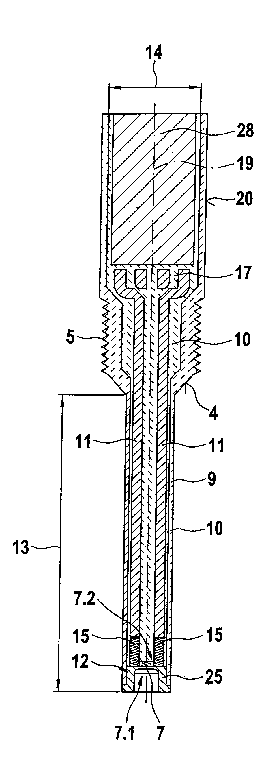
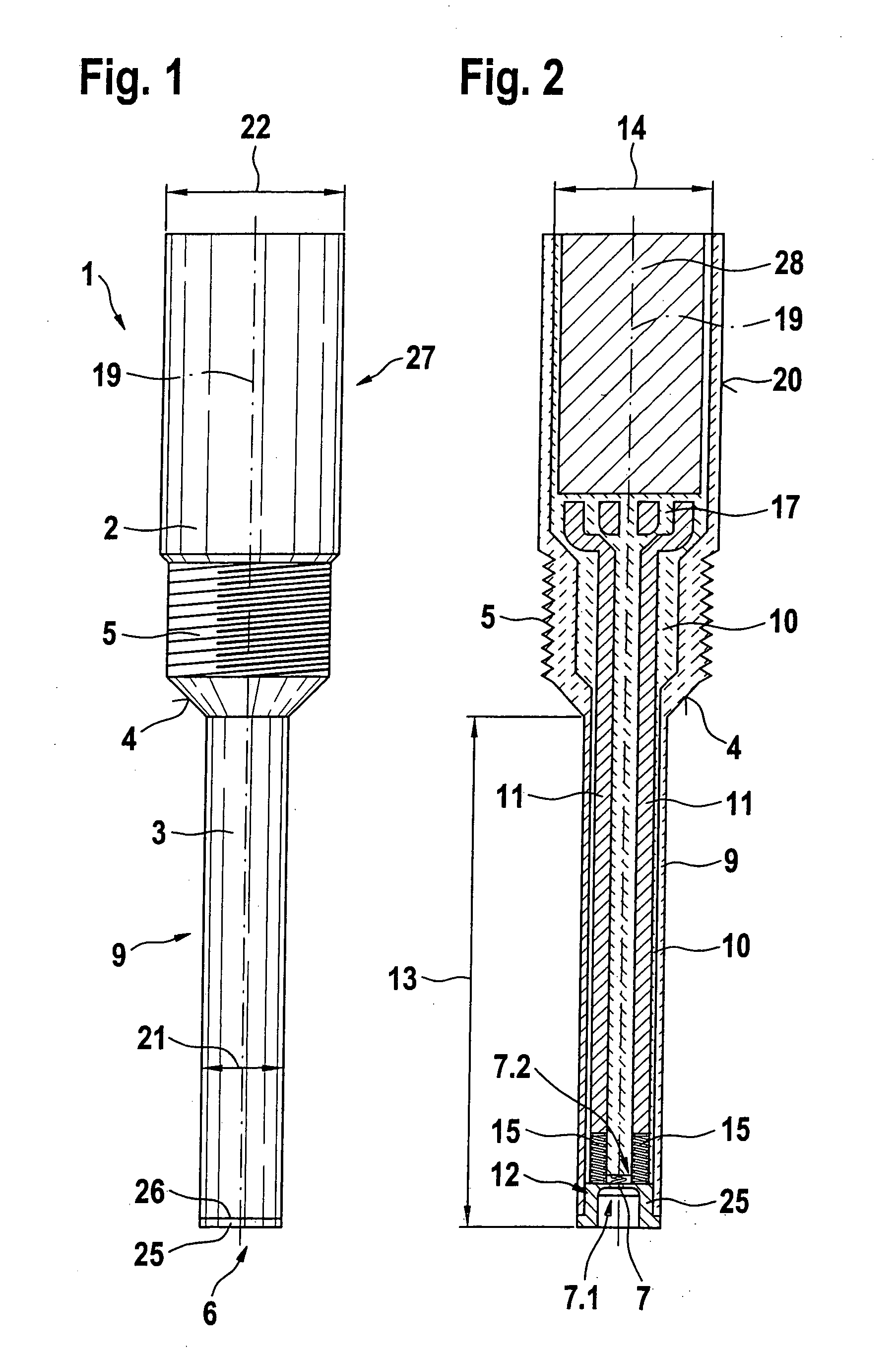
[0015]FIG. 1 shows the plan view of a pressure sensor according to the present invention for spaces acted upon by high pressures.

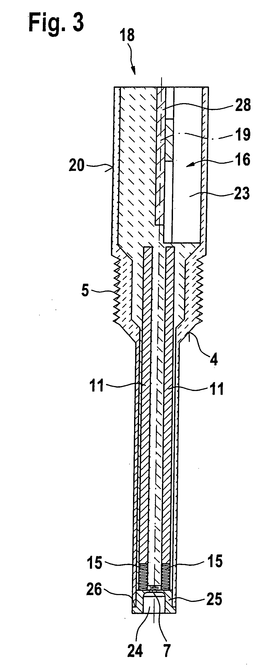
[0016] The pressure sensor shown in FIG. 1 is axially symmetric and includes a sensor neck 3 and a sensor head 27. Evaluation electronics not shown in FIG. 1 are integrated into a sensor body 2 of sensor head 27. A threaded section 5, which ends at a conical sealing seat 4, is provided below sensor body 2 of sensor head 27 of pressure sensor 1. Pressure sensor 1 has a cover tube 9 directly contiguous to conical sealing seat 4, the cover tube forming sensor neck 3. Diameter 21 of sensor neck 3 of pressure sensor 1 according to the representation in FIG. 1 is less than diameter 22 of sensor head 27. An insert 25 is inserted into the end of sensor neck 3 pointing towards the space acted upon by pressure, the insert being able to be welded to the cover tube forming sensor neck 3 or connected to it in a different manner.

[0017] An example narrow design of sens...


PUM

PropertyMeasurementUnit
operating temperaturesaaaaaaaaaa
pressureaaaaaaaaaa
electrically conductiveaaaaaaaaaa

Abstract

A pressure sensor for measuring the pressure in a space acted upon by high pressure. The signals detected by the pressure sensor are supplied to evaluation electronics. A sensor diaphragm is accommodated on the end of the pressure sensor pointing towards the space acted upon by high pressure. The sensor diaphragm takes the form of a steel diaphragm, to whose back side a thin, metallic layer accommodating piezoresistive measuring elements is applied. The thin, metallic layer is contacted by transmission elements and connected to the evaluation electronics.

Description

BACKGROUND INFORMATION [0001] In internal combustion engines of motor vehicles, a pressure measurement for ascertaining the combustion-chamber pressure is necessary, in order to obtain, in each instance, information regarding the pressures prevailing in the combustion chamber of the combustion engine. Information regarding the pressures prevailing in the combustion chambers in each instance may be used for determining the actual engine torque and monitoring the combustion (e.g. misfiring, knock) at in modern engine management systems. [0002] An integrated silicon combustion-chamber pressure sensor is described on page 111 of the kraftfahrttechnischen Taschenbuch Automotive Engineering Paperback Book, 23rd edition, Braunschweig; Wiesbaden, Viehweg 1999, ISBN 3-528-03876-4. The silicon combustion-chamber pressure sensor includes a transmission impacting rod, a silicon platform that is used for applying force, as well as an integrated silicon pressure sensor. Situated on one side of th...

Claims


Application Information

Patent Timeline
Patent Type & Authority Applications(United States)
IPC IPC(8): G01L23/22G01L7/08G01L9/04G01L23/08G01L23/10G01L23/18
CPCG01L23/18
Inventor MOELKNER, THOMASSCHOLZEN, HOLGERGEBERS, JOERGKAISER, RALFKASCHUBE, CARSTENROESSER, CHRISTIANBAUMANN, LOTHARDIDRA, HANS-PETERFREHOFF, ROGERFISSLER, MARKUSLEDERMANN, MARKUSTHIEL, BENJAMIN
Owner ROBERT BOSCH GMBH
Why Eureka
Try Eureka