Firearm projectile apparatus, method, and product by process

a technology of projectiles and projectiles, applied in the field of firearm projectiles, can solve the problems of degeneration of the ballistic qualities of the bullet, more difficult loading, and inability to keep the powder charge out of the gas check in a controlled manner, so as to reduce the assembly surface area of the projectile and minimize the deformation of the bullet 1. , the effect of minimizing the loading impedan

Inactive Publication Date: 2005-02-17
SANBORN CRAIG M
View PDF16 Cites 8 Cited by
  • Summary
  • Abstract
  • Description
  • Claims
  • Application Information

AI Technical Summary

Benefits of technology

[0078] As noted earlier, circumferential belts 110 and 111 wrap part of the outside body of projectile assembly 5 as illustrated in FIG. 8 and elsewhere. They comprise a different, preferably softer, less-dense belt material than bullet 1. Preferably, they comprise a protective lubricant 8 such as discussed above. The employment of a softer, lubricating material in circumferential belts 110 and 111 and of a bullet assembly 5“waist” with a diameter slightly reduced relative to the front and rear diameters (FIG. 9 best illustrates the reduced waist), helps arrive at the proper balance to enable good etching without undue loading impedance, as well as lubrication and bore protection. In short, this substantially reduces the projectile assembly surface area to be engraved at loading, minimizes deformation of bullet 1 during loading, minimizes loading impedance, provides proper seating and etching at both the front and the rear of projectile assembly 5, maintain the firearm bore 9 in good condition without fouling, and enables controlled weight reduction (and weight control

Problems solved by technology

Primary disadvantages of known projectiles for muzzleloaders relate to dimensions of the bullet, placement of the gas check member, and the inability to keep the powder charge out of the gas check in a controlled manner.
Where the bullet's maximum diameter exceeds that of the bore of the firearm, scoring of the bullet from its contact with the rifling as well as deformation of the bullet from the rod-ramming process results, causing degeneration of the ballistic qualities of the bullet.
Additionally, because of the contact between bore and bullet, the firearm is more difficult to load, thereby impeding the loading process when a follow-up shot may be needed in a hurry.
Such wrapping,

Method used


Image

  • Firearm projectile apparatus, method, and product by process
  • Firearm projectile apparatus, method, and product by process
  • Firearm projectile apparatus, method, and product by process

Examples


Embodiment Construction

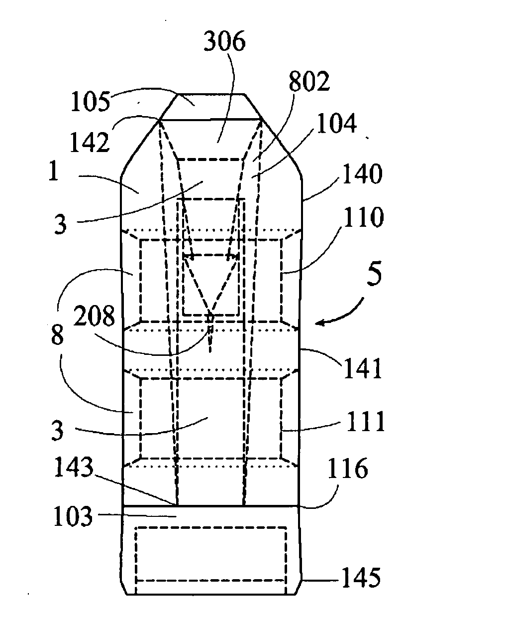
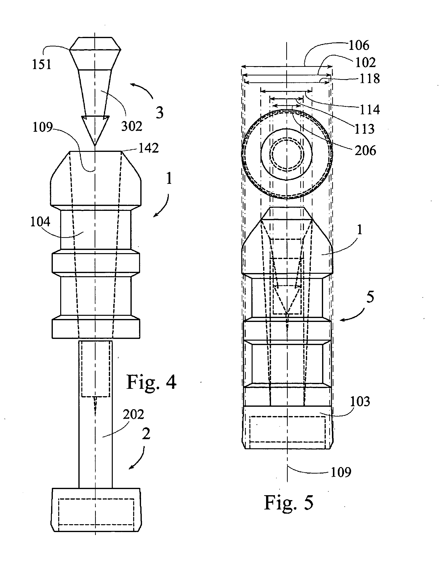
[0017] A firearm projectile assembly apparatus disclosed herein comprises: a bullet; a hollow core running completely through the bullet from a front of the bullet subassembly to a rear of the bullet; a core material within at least part of the hollow core; and an expansion-inducing tip integral with the core material, and protruding forward of the front of the bullet; wherein: when the projectile assembly impacts with a target, the expansion-inducing tip drives the core material rearward relative to the hollow core, forcing the bullet to expand radially outwardly.

[0018] Also disclosed for firearm projectile assembly apparatus is a pressure shield; and a non-discarding attachment of the pressure shield to the bullet, such that after the projectile assembly is fired from a firearm, the pressure shield does not discard from the bullet during the bullet's flight to a target. Also disclosed is a pressure shield comprising: a gas check; and various controlled air spaces.

[0019] Also dis...


PUM


Abstract

A firearm projectile assembly apparatus disclosed herein comprises: a bullet; a hollow core running completely through the bullet from a front of the bullet subassembly to a rear of the bullet; a core material within at least part of the hollow core; and an expansion-inducing tip integral with the core material, and protruding forward of the front of the bullet; wherein: when the projectile assembly impacts with a target, the expansion-inducing tip drives the core material rearward relative to the hollow core, forcing the bullet to expand radially outwardly. Also disclosed for firearm projectile assembly apparatus is a pressure shield; and a non-discarding attachment of the pressure shield to the bullet, such that after the projectile assembly is fired from a firearm, the pressure shield does not discard from the bullet during the bullet's flight to a target. Also disclosed is a pressure shield comprising: a gas check; and various controlled air spaces. Also disclosed are related methods of use and production for the firearm projectile assembly apparatus, and various subassemblies thereof.

Description

TECHNICAL FIELD [0001] This invention relates generally to the field of firearms projectiles, and specifically to projectiles for use in, though not limited to use in, muzzle (front)-loading firearms. BACKGROUND ART [0002] To function most efficiently, muzzle loading firearms preferably have a projectile and a wad or gas check member between the projectile and the powder charge. In the early years of muzzleloaders, a lead projectile was ram-rodded down the bore of the firearm for placement over a powder charge. The diameter of the projectile, of necessity, exceeded the diameter of the bore for holding the projectile in place within the bore. [0003] Later in the history of muzzleloaders came ordnance in which the wad was directly attached to the ball or bullet as typified by U.S. Pat. Nos. 35,273, issued to E. D. Williams and 43,017 issued to G. P. Ganster. [0004] Since the early inventions, it has become common to use sabots or wrappers, surrounding the bullet, to engage the bore of...

Claims


Application Information

Patent Timeline
IPC IPC(8): F42B12/34
CPCF42B12/34
Inventor SANBORN, CRAIG M.
Owner SANBORN CRAIG M
Why Eureka
Try Eureka