Emergency lubrication system

a lubrication system and emergency technology, applied in the direction of efficient propulsion technologies, machines/engines, mechanical devices, etc., can solve the problems of affecting the performance of the engine, so as to prolong the time interval and lighten the weight

Active Publication Date: 2005-02-17
RAYTHEON TECH CORP
View PDF32 Cites 16 Cited by
  • Summary
  • Abstract
  • Description
  • Claims
  • Application Information

AI Technical Summary

Benefits of technology

[0011] One advantage of the invention is that it affords the aircraft crew an interval of time to shut down the affected engine and/or take other actions necessary to safeguard the aircraft and its occupants. The subnormal rate of lubricant release conserves lubricant, t...

Problems solved by technology

If one of the lubrication system components fails, malfunctions or sustains damage, the oil supply to the lubricated component may be disrupted resulting in irreparable damage to the component and undesirable corollary consequences.
For example, if an engine oil pump fails, the resulting loss of oil pressure could disable the engine by causing overheating and/or seizure of the bearings that support the engine shaft.
An aircraft engine that becomes disabled in flight is obviously a concern, especially if the engine powers a single-engine military aircraft operating in hostile airspace.
Otherwise the properties of the reserve lubricant could degrade over time, rendering the lubricant unsuitable for use when called upon in an emergency.
Some known lubrication systems use high pressure to deliver a high ...

Method used


Image

  • Emergency lubrication system
  • Emergency lubrication system
  • Emergency lubrication system

Examples


Embodiment Construction

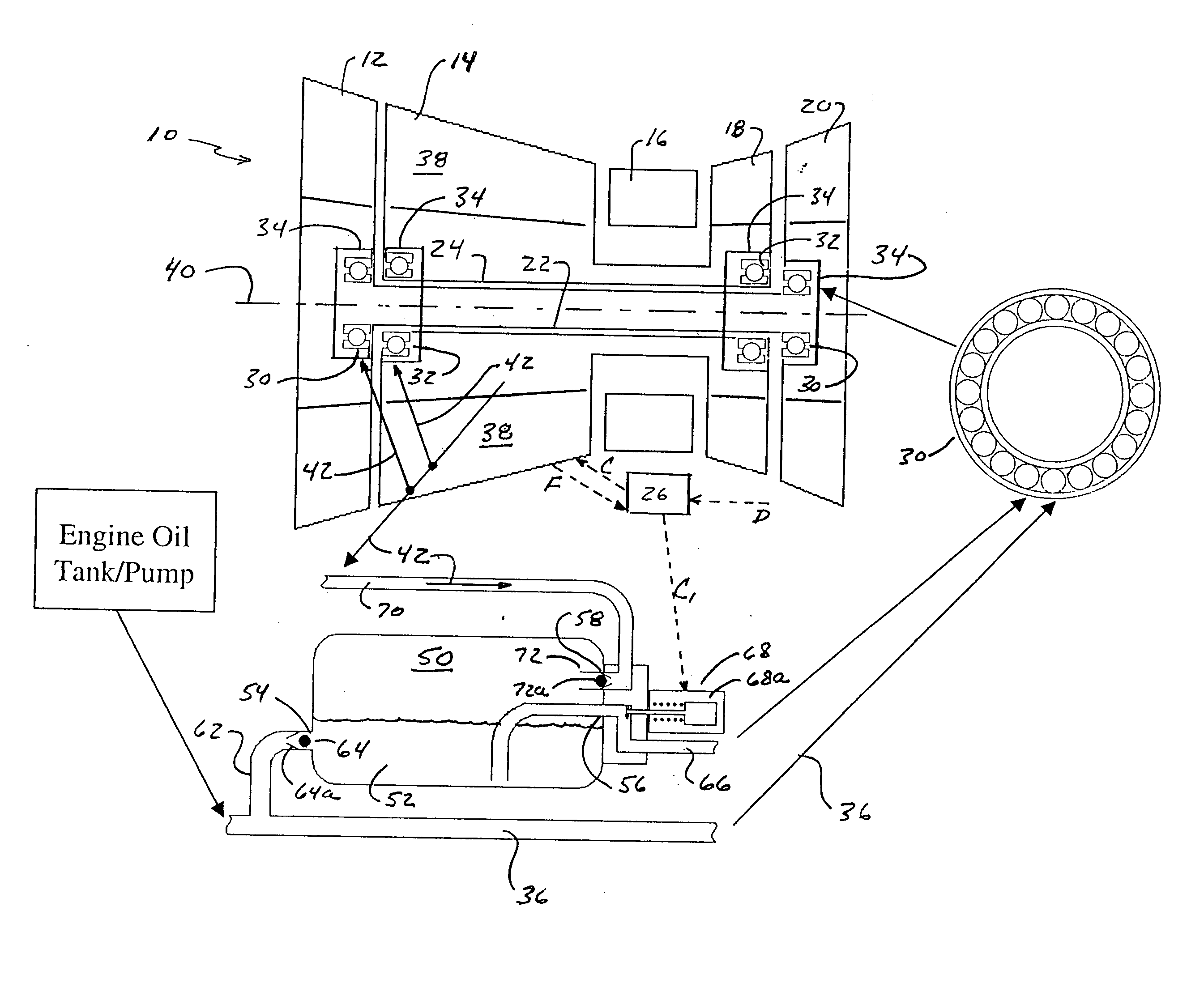
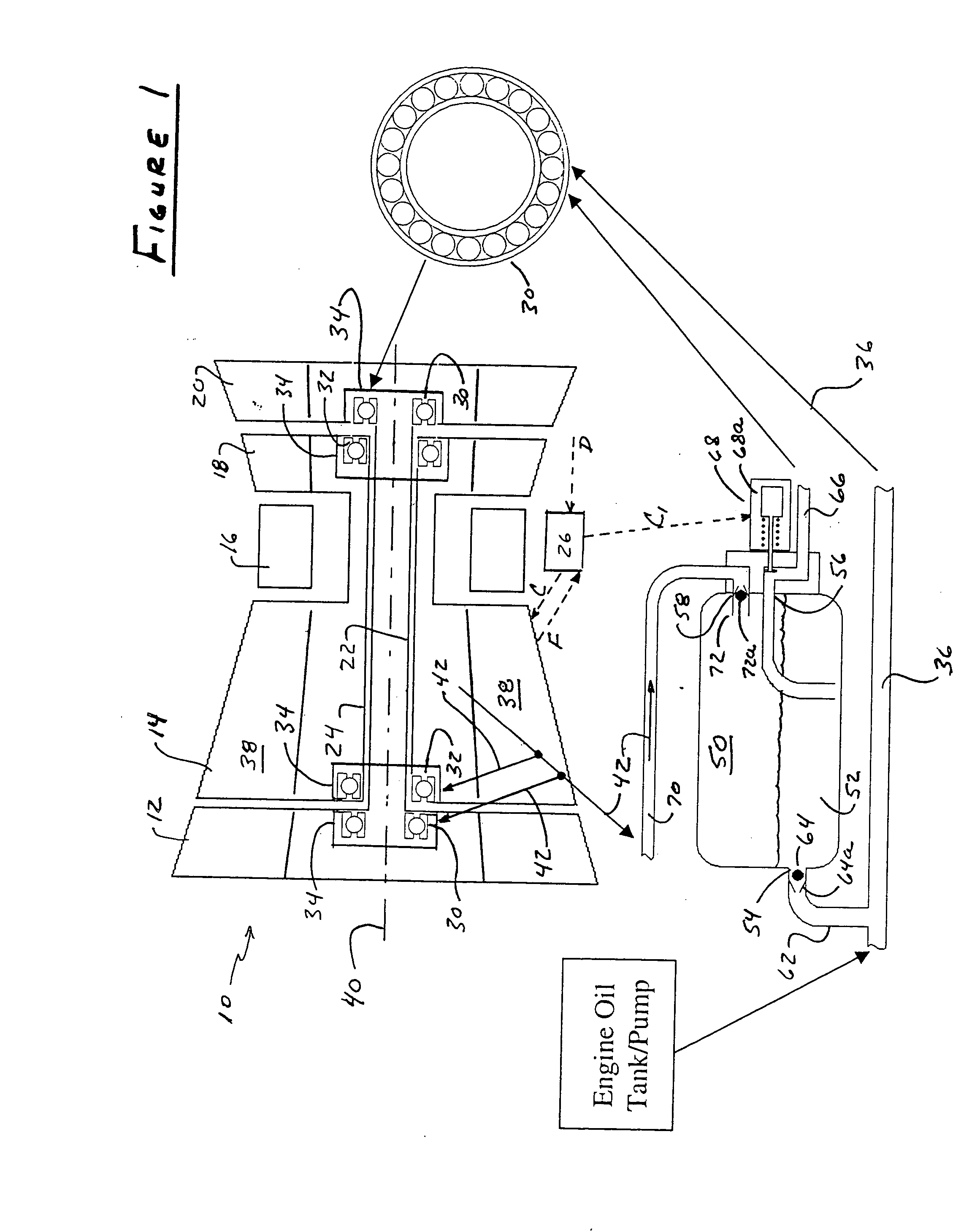
[0016] Referring to FIG. 1, an aircraft gas turbine engine 10 includes low pressure and high pressure compressors 12, 14, a combustor 16, and high pressure and low pressure turbines 18, 20. A low speed shaft 22 couples the low pressure compressor to the low pressure turbine. A high speed shaft 24 couples the high pressure compressor to the high pressure turbine. An engine controller 26 issues control signals C to various engine valves and actuators in response to demand signals D from the aircraft pilot and feedback signals F from the engine.

[0017] Bearings 30 support the low speed shaft from the nonrotatable engine structure. Intershaft bearings 32 support the high speed shaft from the low speed shaft. The bearings are enclosed in bearing compartments 34. A lubrication system, which typically includes an oil tank, pump, filters and deaerators, supplies a lubricant to the bearing compartments, and thus to the bearings, by way of a main lubricant flowpath, which is schematically rep...


PUM


Abstract

An emergency lubrication system for a turbine engine includes a reservoir 50 containing a reserve quantity of lubricant 52 and having a lubricant inlet 54 and a lubricant outlet 56. A lubricant supply line 62 and a lubricant outlet line 66 each have a respective valves 64, 68 for regulating lubricant flow into and out of the reservoir. A fluid supply line 70 includes a valve 72 for selectively establishing communication between the reserve quantity of lubricant and a source of pressurized fluid. During normal operation the lubricant outlet valve continuously releases lubricant at a normal rate to the component requiring lubrication while the lubricant inlet valve concurrently admits fresh lubricant into the reservoir. During abnormal operation, the lubricant inlet valve closes in response to abnormally low lubricant pressure outside the reservoir thereby preventing backflow of reserve lubricant out of the reservoir. The fluid inlet valve opens to admit pressurized fluid into the reservoir thus pressurizing the reserve lubricant. The lubricant outlet valve opens or cycles open and closed in response to a command from a controller 26 so that the pressurized fluid forces lubricant through the outlet 56 as a subnormal rate, which persists until the lubricant reserve is substantially depleted. The subnormal rate is ideally achieved by intermittently releasing lubricant from the reservoir, but may also be achieved by releasing a continuous stream of lubricant at a rate less than the normal rate of release.

Description

STATEMENT OF GOVERNMENT INTEREST [0001] This invention was made under a U.S. Government Contract. The Government has certain rights in the invention.TECHNICAL FIELD [0002] This invention relates to lubrication systems and particularly to a turbine engine lubrication system capable of supplying lubricant for a limited time following a failure or malfunction of a lubrication system component. BACKGROUND OF THE INVENTION [0003] Lubrication systems, such as those used in aircraft gas turbine engines, supply lubricant to bearings, gears and other engine components that require lubrication. The lubricant, typically oil, cools the components and protects them from wear. A typical oil lubrication system includes conventional components such as an oil tank, pump and filter. [0004] If one of the lubrication system components fails, malfunctions or sustains damage, the oil supply to the lubricated component may be disrupted resulting in irreparable damage to the component and undesirable corol...

Claims


Application Information

Patent Timeline
IPC IPC(8): F01D25/18F01D25/20F16N7/38F16N31/00
CPCF01D21/14F05D2270/09Y02T50/671F01D25/18Y02T50/60
Inventor JAMES, DENMAN H.GLAHN, J. AXEL
Owner RAYTHEON TECH CORP
Why Eureka
Try Eureka