
Method and apparatus for purifying mixtures of oil and water

a technology of oil and water mixture and purification method, which is applied in the direction of filtration separation, liquid displacement, separation process, etc., can solve the problems of affecting the pumping process, affecting the effect of the pumping process, so as to achieve the effect of convenient disposal or recycling

Inactive Publication Date: 2005-02-17
CHEM MANAGEMENT SYST
View PDF18 Cites 15 Cited by
  • Summary
  • Abstract
  • Description
  • Claims
  • Application Information

AI Technical Summary

Benefits of technology

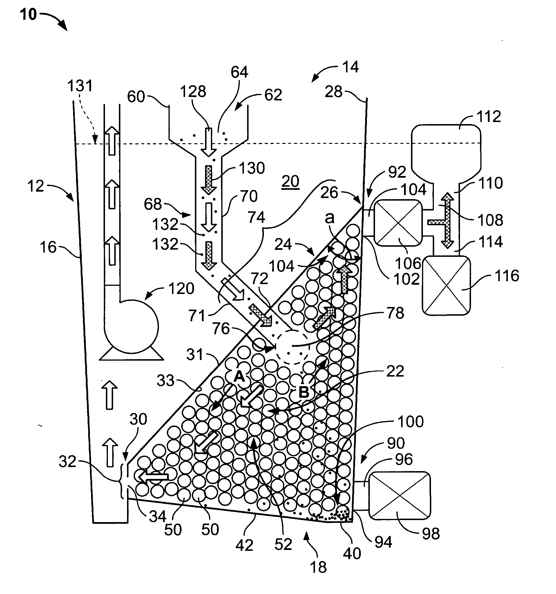
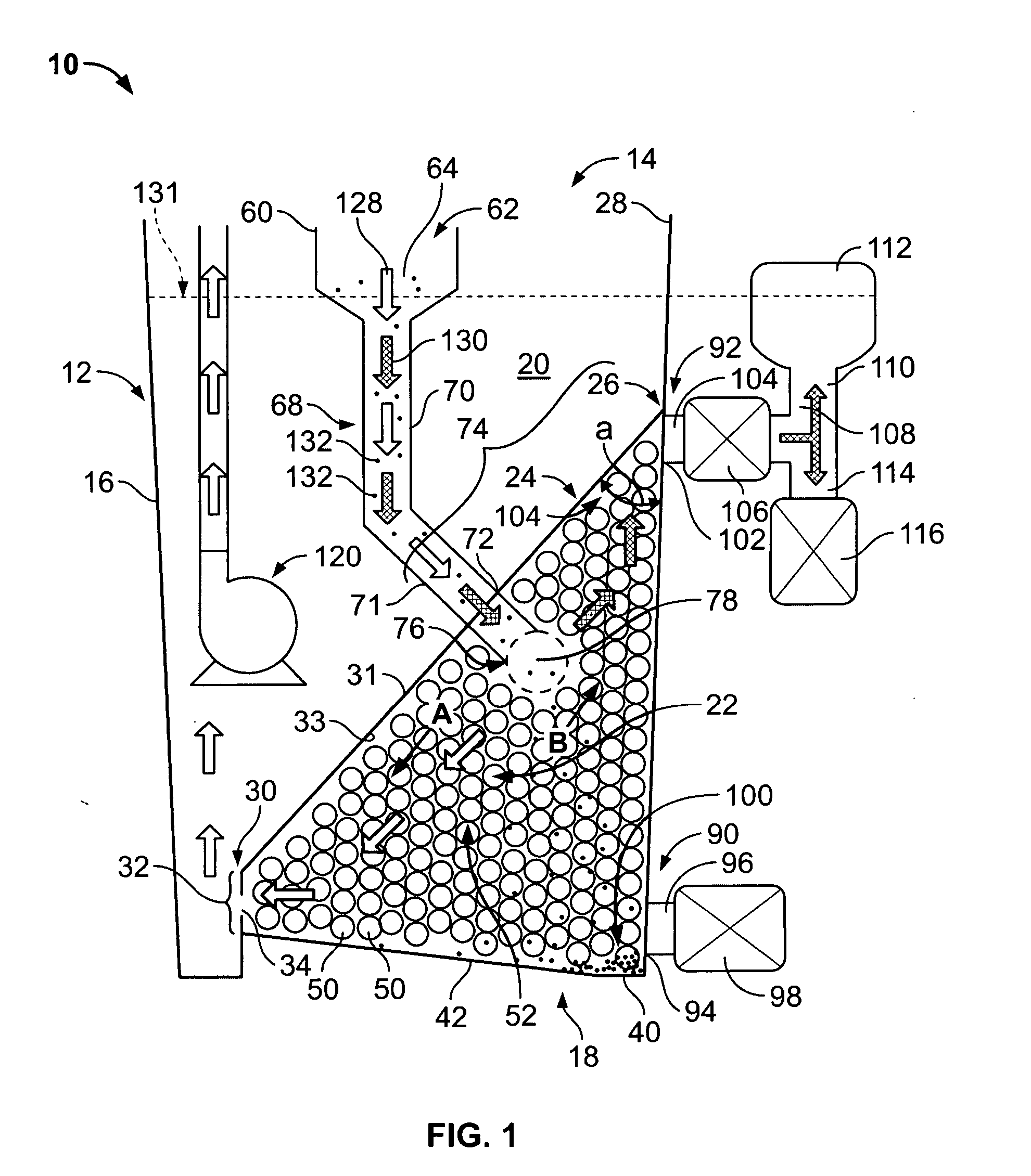
[0012] In the present process, purification of contaminated aqueous industrial process fluids may be accomplished by passing the fluids through coalescing media positioned in a process tank during normal recirculation of the fluid as it leaves the workstation after performing its intended degreasing / washing or metalworking lubrication / cooling functions and passes into a collection reservoir. The aqueous fluid used in the process flows through a drain to an area where it enters into a coalescing media and passes generally downward along a weir plate on its way to returning to the already present process pump. The weir plate establishes a demarcation separating the clean side (top) of the tank from the dirty side (bottom). As the aqueous fluid is drawn to the pump due to the pressure differential created by the pump's suction, it is drawn through the coalescing media. Viscosity differences between the oil-based contaminants and the aqueous phase cause the oil and aqueous phases to separate and the oil (and any other lighter-than-water components) to rise. The rising oil is intercepted by the weir plate and diverted to a reservoir where it can be collected and readily disposed of or recycled.

Problems solved by technology

Such fluids are quickly contaminated with increasing amounts of emulsified oils, free oils, particulate matter, suspended solids, and other contaminants that degrade their effectiveness and can impede the pumping process.
These approaches often result in unnecessary expense since they require additional pumping devices, tanks, filters, etc.

Method used


Image

  • Method and apparatus for purifying mixtures of oil and water
  • Method and apparatus for purifying mixtures of oil and water
  • Method and apparatus for purifying mixtures of oil and water

Examples


Embodiment Construction

[0023]FIG. 1 is a diagrammatic representation of one separator unit 10 in accordance with the present invention and its method of operation. Separator unit 10 comprises a tank or container 12 having a generally open top 14, a side 16 encircling the generally cylindrical unit and a closed bottom 18. The tank may be made in any appropriate shape or of any appropriate material such as an appropriate plastic resin, stainless steel, etc.

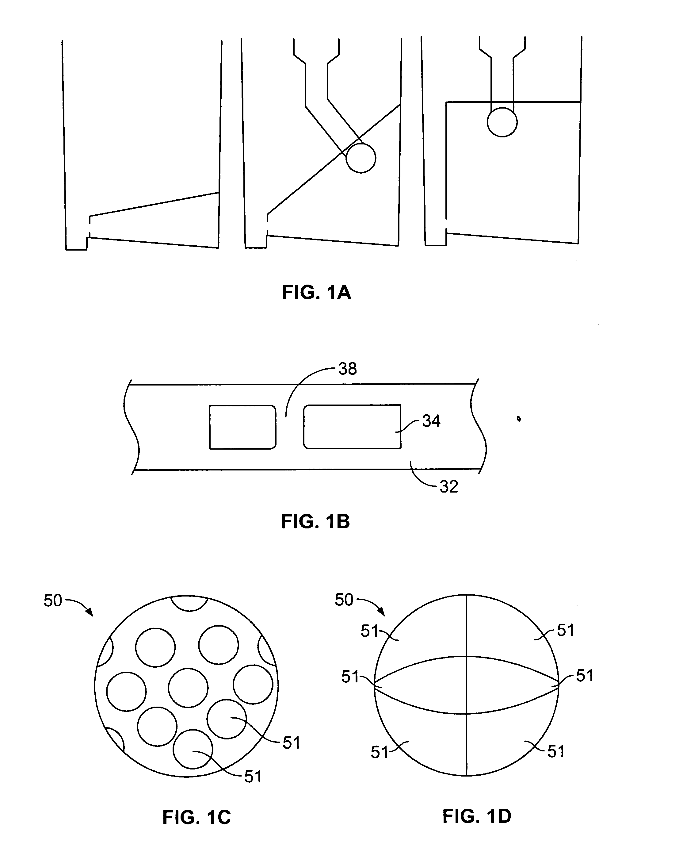
[0024] Tank 12 has a weir plate 24 that may be viewed as dividing tank 12 into an upper clean fluid compartment 20 and a lower separation compartment 22. Weir plate 24 is dimensioned so that it generally abuts the inner surface 28 of the tank along the top edge or upper periphery 26 of the plate. Weir plate 24 can be fixed in position by welding, molding-in-place, adhesives or other appropriate means. The lower edge 30 of the weir plate is spaced from inner surface 28 of the tank and is provided with a downwardly directed lip 32.

[0025] While weir plate ...


PUM

PropertyMeasurementUnit
Angleaaaaaaaaaa
Angleaaaaaaaaaa
Diameteraaaaaaaaaa

Abstract

An apparatus and method for separating oil and particulate contaminants from pump-driven aqueous fluid contaminated with emulsified oils, free oils, particulate matter, suspended solids, and other contaminants in which the contaminated fluids are introduced into a container having a horizontal bottom portion and a weir plate dividing the container into an upper clean fluid compartment and a lower separation compartment, an aperture for the outflow of clean fluid from the upper clean fluid compartment sized relative to the pumping rate of the pump driving the aqueous fluid to ensure a residence time of the contaminated fluid in the lower separation compartment of at least about 0.4 minutes, coalescing media comprising a plurality of abutting polypropylene spheres located in the lower separation compartment, and a drain receptacle for collecting the contaminated fluid and delivering the contaminated fluid across the weir plate to the lower separation compartment.

Description

CROSS-REFERENCE TO RELATED APPLICATIONS [0001] This application claims the benefit of U.S. Provisional Application Ser. No. 60 / 494,217, filed Aug. 8, 2003.BACKGROUND OF THE INVENTION [0002] This invention relates generally to methods and apparatus for recycling contaminated fluids, and, more particularly, to an improved method and apparatus for separating oil and particulate contaminates from pump-driven aqueous fluid contaminated with emulsified oils, free oils, particulate matter, suspended solids, and other contaminants. [0003] Aqueous-based industrial process fluids such as degreasing / washing chemicals or metalworking fluids are frequently applied by pumping the fluids through a process pump to transport it through plumbing and nozzles to a workstation where the intended degreasing / washing or metalworking lubrication and cooling are performed before the fluid is collected and sent back through the system again. Such fluids are quickly contaminated with increasing amounts of emul...

Claims


Application Information

Patent Timeline
IPC IPC(8): B01DB01D17/00B01D24/38
CPCB01D17/00Y10S210/05B01D17/0208B01D17/0211B01D17/0214B01D17/045B01D17/12
Inventor LINDSEY, TIMOTHY C.PICKOWITZ, JOSEPHRUNDELL, STEPHEN
Owner CHEM MANAGEMENT SYST
Learn More