Apparatus and method for large hardware finite state machine with embedded equivalence classes

a finite state machine and hardware technology, applied in the field of integrated circuits, can solve the problems of sacrificing content delivery or network security, increasing the amount of memory needed to store this data, and qos and signature-based security services finding it increasingly difficult to keep up with the demands of matching packet content,

Inactive Publication Date: 2005-02-17
INTEL CORP +1
View PDF6 Cites 49 Cited by
  • Summary
  • Abstract
  • Description
  • Claims
  • Application Information

AI Technical Summary

Benefits of technology

In some embodiments, the FSM includes a pipeline register disposed between the first address calculation logic block and the first lookup table, a second pipeline register disposed between the first lookup table and the second address calculation logic block, and a third pipeline register disposed between the second address calculation logic block and the second lookup table. The pipeline registers are adapted to process multiple data streams concurrently by having a different data stream occupy each pipeline stage. Data at each pipeline stage is passed forwards through that pipeline. Since multiple streams are being processed concurrently, throughput is improved.
In accordance with the present invention, redundancy within the blocks of the transition table is used for efficient storage of data in the lookup tables. Therefore, bits from input symbol and current state are combined in order to supply address to the first lookup table so as to achieve greater throughput and reduce the need for memory capacity. Given that there are 2n+k entries in these transition table for n-bit states and k-bit symbols, grouping the transition table entries into blocks of 2q, allows the first lookup table to have 2n+k−q locations, addressed by a (n+k−q)-bit address. The number of locations in the second look-up table is determined by the redundancy in the state transition table.
In one embodiment, the first address calculation logic block (405 or 505) uses k−q bits of the input symbol and the n-bit current state to generate an (k−q+n)-bit address to the first lookup table. The remaining q bits of the input symbol are used by the second address calculation logic block. Generating the address for the first lookup table address in this manner, enables portioning the table along its rows into blocks each having 2q entries. In another embodiment, the first address calculation logic block uses k bits of the input symbol and (n−q) bits from the current state to generate an (n−q+k)-bit address to the first lookup table. The remaining q bits of the current state are used by the second address calculation logic unit. Generating the address for the first lookup table address in this manner, enables portioning the table along its columns into blocks each having 2q entries. In yet another embodiment, the first address calculation logic block uses (k−p) bits of the input symbol and (n−q) bits from the current state to generate an (k+n−q−p)-bit address to the first lookup table. The remaining (q+p) bits of the input symbol and current state are used by the second address calculation logic block. Generating the address for the first lookup table address in this manner, enables portioning the table along its columns or rows into blocks each having 2q+p entries.

Problems solved by technology

As network speeds increase, QoS and signature-based security services are finding it increasingly more challenging to keep up with the demands of the matching packet content.
The services therefore sacrifice content delivery or network security by being required to miss packets.
However as the number of data related to the states, input symbols and transitions become large, the amount of memory needed to store this data grows exponentially.
Programmable FSMs are often expensive because of the size of the memory required to store the transition table.
This problem is even more pronounced for fast FSMs which are required to compute the next state within a few and fixed number of clock cycles.
This technique also suffers from the problem that the stack memory is limited.

Method used


Image

  • Apparatus and method for large hardware finite state machine with embedded equivalence classes
  • Apparatus and method for large hardware finite state machine with embedded equivalence classes
  • Apparatus and method for large hardware finite state machine with embedded equivalence classes

Examples


Embodiment Construction

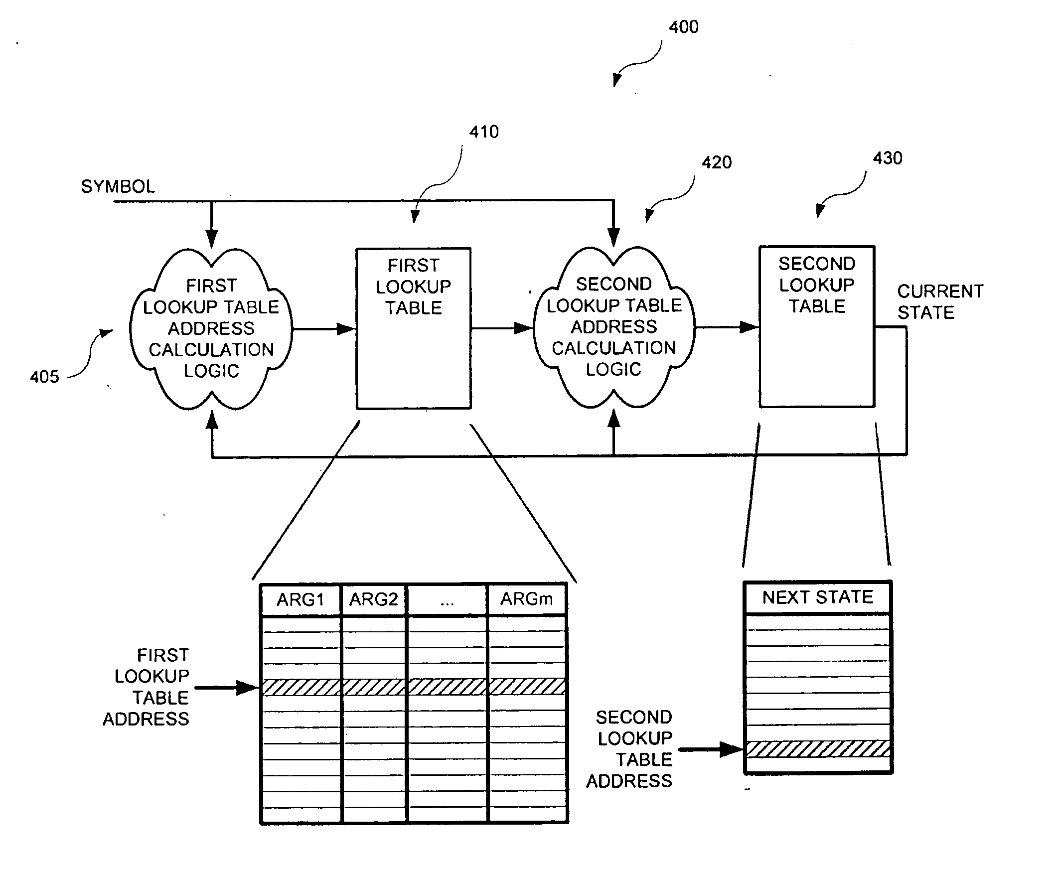
FIG. 4 is a simplified high-level block diagram of a programmable finite state machine (FSM) 400, in accordance with one embodiment of the present invention. Programmable FSM 400 is shown as including a first address calculation logic 405, a first lookup table 410, a second address calculation logic 420, a second lookup table 430. As described further below, FSM 400 has a high throughput and uses a relatively smaller memory to store the state transitions data than those known in the prior art.

In the following, k is the number of bits required to represent each symbol, n is the number of bits required to represent each state within the FSM, and q is the number of bits used within each block when partitioning the FSM transition table. Thus, the total number of states is 2n, and each block contains 2q entries. For example, up to 256 symbols may be represented if k is equal to 8.

First address calculation logic 405 is configured to receive a k-bit input symbol data and an n-bit curren...


PUM


Abstract

A programmable finite state machine (FSM) includes, in part, a first address calculation logic block, a first lookup table, a second address calculation logic block, and a second lookup table. The first address calculation logic block generates an address for the first lookup table based on the received input symbol and the current state. The data stored in first look-up table at the generated address is used by the second address calculation logic block to compute an address for the second lookup table. Data stored in the second lookup table is the next state to which the FSM transitions. The programmable FSMs uses redundant information of the transition table to compress these transitions and thus requires a smaller memory while maintaining a high data throughput. The data in the first and second lookup tables are coded and supplied by a compiler. The FSM operation may optionally be pipelined.

Description

FIELD OF THE INVENTION The present invention relates to integrated circuits, and more particularly to programmable finite state machines with high throughput. BACKGROUND OF THE INVENTION Deep content inspection of network packets is driven, in large part, by the need for high performance quality-of-service (QoS) and signature-based security systems. Typically QoS systems are configured to implement intelligent management and deliver content-based services which, in turn, involve high-speed inspection of packet payloads. Likewise, signature-based security services, such as intrusion detection, virus scanning, content identification, network surveillance, spam filtering, etc., involve high-speed pattern matching on network data. The signature databases used by these services are updated on a regular basis, such as when new viruses are found, or when operating system vulnerabilities are detected. This means that the device performing the pattern matching must be programmable. As ne...

Claims


Application Information

Patent Timeline
Patent Type & Authority Applications(United States)
IPC IPC(8): G06FG06F7/38G06F9/44G06F17/50H01L
CPCG06F9/444G06F9/4498
Inventor GOULD, STEPHENPELTZER, ERNESTBARRIE, ROBERT MATTHEWFLANAGAN, MICHAELWILLIAMS, DARREN
Owner INTEL CORP
Why Eureka
Try Eureka