Methods for producing a nozzle plate and nozzle plate

a technology of nozzle plate and nozzle plate, which is applied in the direction of printing, photomechanical treatment, instruments, etc., can solve the problems of inability to produce film, inability inability to reduce the amount of projection due to the overhanging of the water-repellent film, so as to prevent ink leakage, improve the water-repellent neighbor of the nozzle ejection port, and reduce the amount of projection

Active Publication Date: 2005-02-17
BROTHER KOGYO KK
View PDF5 Cites 19 Cited by
  • Summary
  • Abstract
  • Description
  • Claims
  • Application Information

AI Technical Summary

Benefits of technology

A part of the columnar cured portion protrudes from the surface of the substrate and has the outer diameter equal to or smaller than the inner diameter of the ink ejection port. Thus, a region where the water-repellent film is not formed is not formed in the neighbor of the ink ejection port of a nozzle. Furthermore, a projection amount due to an overhanging of the water-repellent film can be reduced. Accordingly, the water-repellency in the neighbor of the ink ejection port of the nozzle is improved, so that leakage of the ink can be prevented. In addition, the ink ejected from the nozzle does not interfere with the water-repellent film, so that the ink impact accuracy is improved.
According to one embodiment of the invention, a nozzle plate includes a nozzle from which ink are ejected, and a water-repellent film on a surface of the nozzle plate. The water-repellent film includes an opening portion, an area of which is equal to an opening area of the nozzle, at a position of the nozzle. The opening portion of the water-repellent film has an edge along the nozzle. As described above, the nozzle plate is configured so that the opening area of the opening portion formed in the water-repellent film is equal to the opening area of the nozzle, and the opening portion of the water-repellent film has the edge along the nozzle. Therefore, an ink ejected from the nozzle does not interfere with the water-repellent film. Also, the water-repellent film is formed along the ink ejection port of the nozzle, so that the ink impact accuracy is improved.

Problems solved by technology

Hence, there arises the possibility that the water repellency is impaired and the ink impact accuracy is lowered.
However, a so-called overhang in which the nozzle is partly covered by the water-repellent film is inevitably formed.
The ink ejected from the nozzles interferes with the overhang portion of the water-repellent film.

Method used


Image

  • Methods for producing a nozzle plate and nozzle plate
  • Methods for producing a nozzle plate and nozzle plate
  • Methods for producing a nozzle plate and nozzle plate

Examples


first embodiment

[First Embodiment]

A first embodiment of the invention will be described. In the first embodiment, the invention is applied to a nozzle plate, which is to be disposed in an ink jet head and includes a nozzle for ejecting ink. Hereinafter, the first embodiment will be described with reference to FIG. 1.

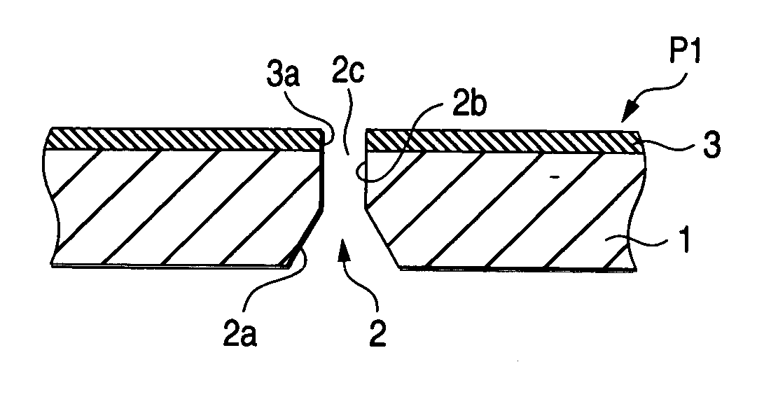
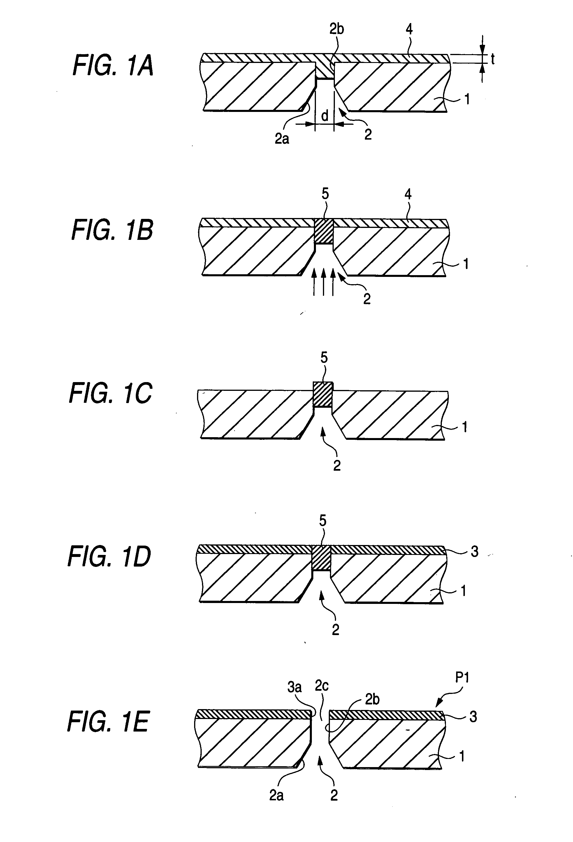
First, a nozzle plate P1 will be briefly described. As shown in FIG. 1E, the nozzle plate P1 includes: a nozzle 2 which is formed in a substrate 1, and from which ink is to be ejected; and a water-repellent film 3 which is formed on the surface (the face on the ink ejection side) of the substrate 1. The substrate 1 is formed of a sheet of a metal (for example, stainless steel), and has a thickness of, for example, about 70 μm. The nozzle 2 has: a taper portion 2a which is formed on the side of the rear face of the substrate 1 and is more tapered as further advancing toward the surface; and a straight portion 2b which elongates from the taper portion 2a to the surface of the substrate...

example 1

The above-described methods of producing a nozzle plate were checked by the following method. A nozzle including a ejection port having an inner diameter of 20 μm was formed in a substrate made of SUS430 having a thickness of 75 μm. Then, a photocuring resin film was pressure bonded to the surface of the substrate at a pressure of 0.2 MPa (about 2 kg / cm2) under the state where the film was heated to 70° C. In the pressure bonding of the photocuring resin film, a roller is moved at movement velocity 1 m / min twice to apply the pressure of 0.2 MPa to the surface of the substrate. As the photocuring resin film, Ohdil (dry film photoresist) FP215 (glass transition point Tg: an initiating temperature of 65° C. and an ending temperature of 95° C.) produced by TOKYO OHKA KOGYO CO., LTD. was used. The thickness thereof was 15 μm. The photocuring resin film was substantially hardened by an exposure amount of 100 mJ / cm2. Under this state, light irradiation was conducted while changing the exp...

second embodiment

Next, a second embodiment of the invention will be described. The portions which are similarly configured as those of the first embodiment are denoted by the same reference numerals, and their description is adequately omitted. Hereinafter, description will be made with reference to FIG. 5.

First, a nozzle plate P3 will be briefly described. As shown in FIG. 5F, the nozzle plate P3 includes: a nozzle 2 which is formed in a substrate 1, and from which ink is to be ejected; and a water-repellent film 3 which is formed on the surface (the face on the ink ejection side) of the substrate 1. On a rear side of the substrate 1, a flat polished surface 6 is formed.

Next, a method for producing the nozzle plate P3 will be described. First, as shown in FIG. 5A, a surface polishing process is applied to all over the rear surface side of the substrate 1 to form the polished surface 6 (see an arrow in FIG. 5A: a polishing step). When the taper portion 2a of the nozzle 2 is formed by a process ...


PUM


Abstract

A method for producing a nozzle plate includes the following steps. A photocuring resin is applied onto a surface of a substrate that includes a nozzle while an ink ejection port of the nozzle being filled with the photocuring resin. Light is irradiated to the photocuring resin from a rear surface of the substrate through the nozzle to form a columnar cured portion. The columnar cured portion includes a head portion and a base portion. The head portion protrudes from the surface of the substrate and has an outer diameter equal to or smaller than an inner diameter of the ink election port. The base portion is disposed in the nozzle and has an outer diameter equal to the inner diameter of the ink ejection port. The photocuring resin except for the columnar cured portion is removed. A water-repellent film is formed on the surface of the substrate.

Description

BACKGROUND OF THE INVENTION 1. Field of the Invention The present invention relates to a method of producing a nozzle plate including a nozzle for ejecting ink, and also to such a nozzle plate. 2. Description of the Related Art An ink jet head includes a nozzle plate formed with nozzles, and ejects ink from the nozzles onto a recording medium to perform a printing process. In the case where the peripheral portion of ink ejection ports of the nozzles has poor water repellency (ink repellency) and gets wetting with ink, the ink may adhere to the peripheral portion of the ink ejection ports and remain there. Furthermore, the ejected ink interfere with the ink adhering to the peripheral portion of the ink ejection ports to lower the ink impact accuracy. Therefore, a water-repellent film which can improve the water repellency is formed on the surface (the ink ejection side) of a substrate of the nozzle plate. Various methods of forming such a water-repellent film on the surface of a ...

Claims


Application Information

Patent Timeline
Patent Type & Authority Applications(United States)
IPC IPC(8): B41J2/135B41J2/16
CPCB41J2/1606B41J2/162B41J2/1643B41J2/1631B41J2/1632B41J2/1623
Inventor KITAHARA, SEIKOKOBAYASHI, YASUNORIITO, ATSUSHI
Owner BROTHER KOGYO KK
Why Eureka
Try Eureka